Integrated circuit package stacking system

a technology of integrated circuits and stacking systems, applied in the direction of electrical equipment, semiconductor devices, semiconductor/solid-state device details, etc., can solve the problems of reducing the reliability of the solder joint, increasing the susceptibility to solder cracking, and the elastic minimum of the solder connection properties

Active Publication Date: 2010-02-04
STATS CHIPPAC LTD
View PDF14 Cites 80 Cited by
  • Summary
  • Abstract
  • Description
  • Claims
  • Application Information

AI Technical Summary

Problems solved by technology

However, when solder alone is used to interconnect the chip contacts to the substrate, the columns of solder are generally designed to be short to maintain the solder's structural integrity.
This results in minimal elastic solder connection properties, which further results in increased susceptibility to solder cracking due to the mechanical stress of the differential coefficient of thermal expansion (“CTE”) of the chip relative to the supporting substrate, thereby reducing the reliability of the solder joint.
The problem that arises is that the chip and the substrate expand and contract at different rates and at different times, thereby stressing the interconnections between them.
The solder cracking problem is exacerbated when more than one semiconductor chip is mounted in a package, such as in a multichip module.
Multichip modules continue to grow in popularity; however, as more chips are packaged together, more heat will be dissipated by each package which, in turn, means the interconnections between a package and its supporting substrate will encounter greater mechanical stress due to thermal cycling.
Another issue for the multichip modules is manufacturability.
As the number of integrated circuits in the package increases, it becomes more difficult to achieve good manufacturing yields.
A single failed component included in the stack will make the entire stack bad.
Solutions to these problems have been long sought but prior developments have not taught or suggested any solutions and, thus, solutions to these problems have long eluded those skilled in the art.

Method used


Image

  • Integrated circuit package stacking system
  • Integrated circuit package stacking system
  • Integrated circuit package stacking system

Examples


Embodiment Construction

[0027]The following embodiments are described in sufficient detail to enable those skilled in the art to make and use the invention. It is to be understood that other embodiments would be evident based on the present disclosure, and that process or mechanical changes may be made without departing from the scope of the present invention.

[0028]In the following description, numerous specific details are given to provide a thorough understanding of the invention. However, it will be apparent that the invention may be practiced without these specific details. In order to avoid obscuring the present invention, some well-known circuits, system configurations, and process steps are not disclosed in detail. Likewise, the drawings showing embodiments of the system are semi-diagrammatic and not to scale and, particularly, some of the dimensions are for the clarity of presentation and are shown greatly exaggerated in the drawing FIGs. Where multiple embodiments are disclosed and described, havi...


PUM


Abstract

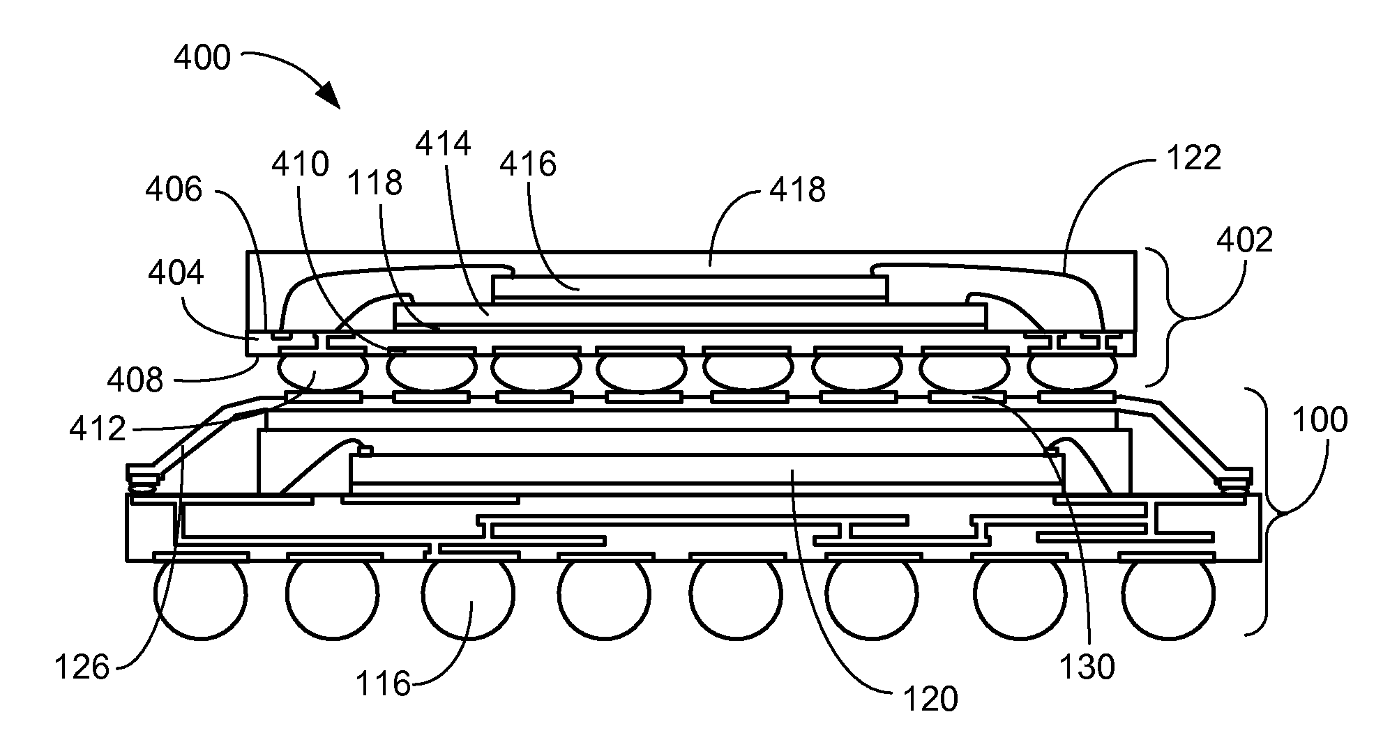
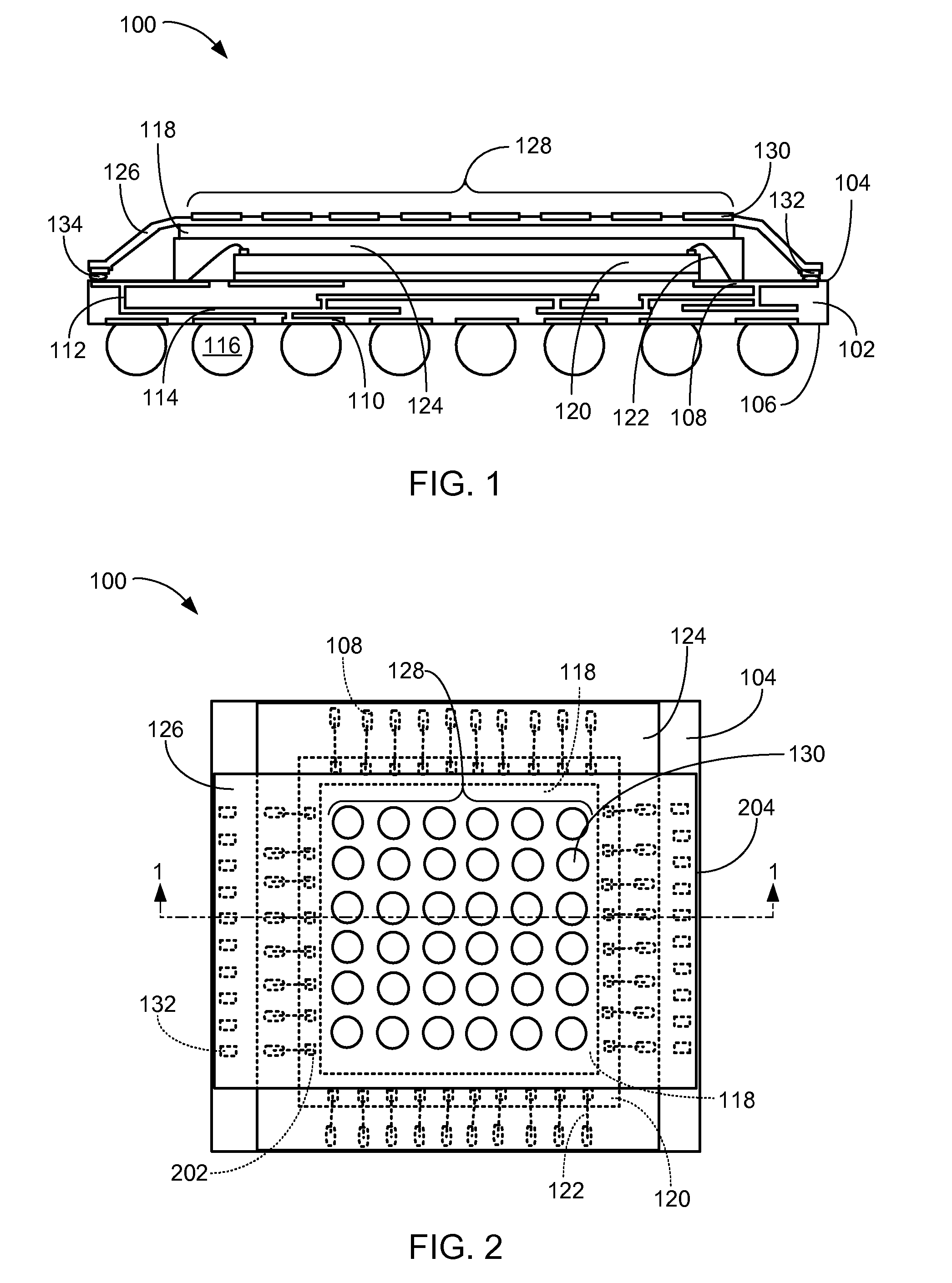
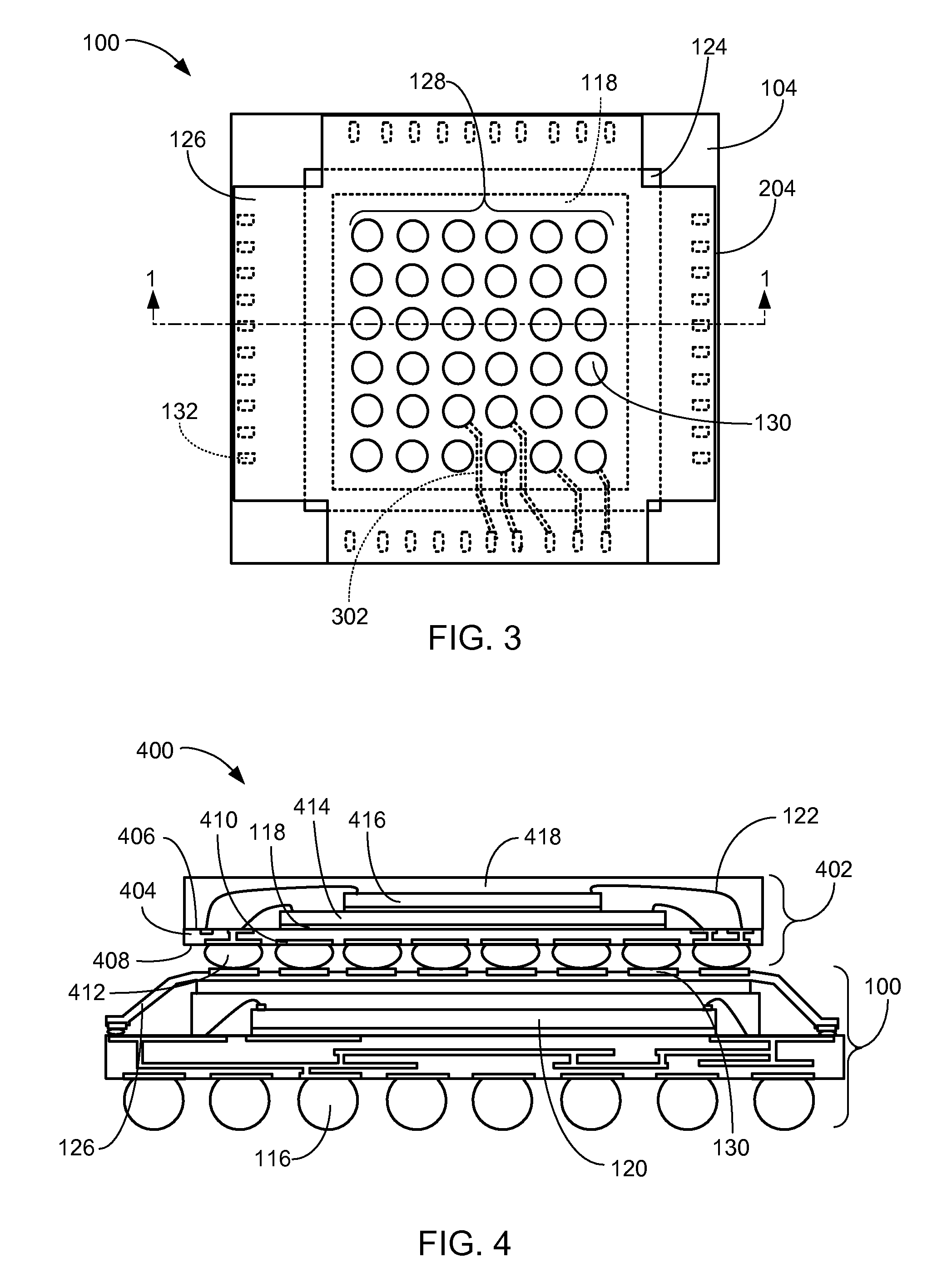
An integrated circuit package stacking system includes: forming a flexible substrate by: providing an insulating material, forming a stacking pad on the insulating material, forming a coupling pad on the insulating material, and forming a trace between the stacking pad and the coupling pad; providing a package substrate; coupling an integrated circuit to the package substrate; and applying a conductive adhesive on the package substrate for positioning the flexible substrate over the integrated circuit and coupling the flexible substrate on the conductive adhesive.

Description

TECHNICAL FIELD[0001]The present invention relates generally to integrated circuit packaging, and more particularly to a system for stacking integrated circuit packages.BACKGROUND ART[0002]Many of today's shrinking consumer electronic devices, such as cellular telephones, digital video cameras, global positioning systems, personal audio / video players, and personal data assistants, require many functions to be packaged in a very small area of a printed wiring board. In attempting to use the area on the printed wiring boards more efficiently, semiconductor chip manufacturers have recently been switching from larger, more cumbersome interconnection conventions, such as pin grid arrays (“PGAs”) and the perimeter leaded quad flat packs (“QFPs”), to smaller conventions, such as ball grid arrays (“BGAs”). Using BGA technology, semiconductor chips are typically interconnected to their supporting substrates using solder connections, such as with “flip-chip” technology. However, when solder a...

Claims


Application Information

Patent Timeline
Patent Type & Authority Applications(United States)
IPC IPC(8): H01L23/538H01L21/58
CPCH01L23/49816H01L23/4985H01L2924/07802H01L2225/1058H01L2225/1041H01L2225/1023H01L2224/48227H01L2224/32225H01L2924/3025H01L2924/3011H01L2924/19107H01L2924/15331H01L2924/15311H01L2924/14H01L2225/06579H01L2225/06568H01L2224/73265H01L2224/73215H01L2224/73204H01L2224/49175H01L2224/48225H01L2224/48091H01L2224/32145H01L2224/2919H01L25/105H01L25/0657H01L25/03H01L24/48H01L24/31H01L2924/00014H01L2924/0665H01L2924/00H01L2924/3512H01L2924/00012H01L24/73H01L2924/181H01L2224/05554H01L24/49H01L2224/45099H01L2224/45015H01L2924/207
Inventor OH, JIHOONKIM, JINGWANLIM, JAEHYUNCHUN, SUNYOUNGLEE, KYUWONLEE, SINJAEPARK, JONGVIN
Owner STATS CHIPPAC LTD
Why Eureka
Try Eureka