Wave energy harnessing device

Active Publication Date: 2010-02-04
STEVENS INSTITUTE OF TECHNOLOGY
View PDF68 Cites 32 Cited by
  • Summary
  • Abstract
  • Description
  • Claims
  • Application Information

AI Technical Summary

Benefits of technology

[0004]The present invention overcomes the short-comings described above by providing a wave energy harnessing devices having optimized functionality that applies real time adjustments in response to real time changes in wave characteristics, so as to optimize the energy extracted from the waves. The wave energy harnessing device has a surface flotation device with a line attached to a reel positioned on a submerged buoyant-platform, which itself is anchored to the sea floor. The flotation device line is wrapped around the reel. Lift from the floatation device and load from a power take-off system induce reciprocating rotary motion on the reel as waves pass by the flotation device. The lift from the floatation device inputs energy to the power take-off system, causing the reel to rotate in one direction, and the power take-off system acts as a spring to rewind the reel after the wave passes under the floatation device, causing the reel to rotate in the opposite direction. Since more energy is required to lift the floatation device than to rewind the reel, there is a net gain in energy stored in the power take-off system from each wave cycle. The energy gained can be used to operate the electrical generating equipment mounted on the platform. The submerged buoyant platform is maintained in a submerged position by ancho

Problems solved by technology

The finite supply and environmental issues associated with fossil fuels have resulted in the need for alternate energy sources.
The decline in fossil fuel sources, difficulty in obtaining those fossil fuels, and environmental impacts of their use have lead to instability in the energy markets.
None of these devices, howe

Method used


Image

  • Wave energy harnessing device
  • Wave energy harnessing device
  • Wave energy harnessing device

Examples


Embodiment Construction

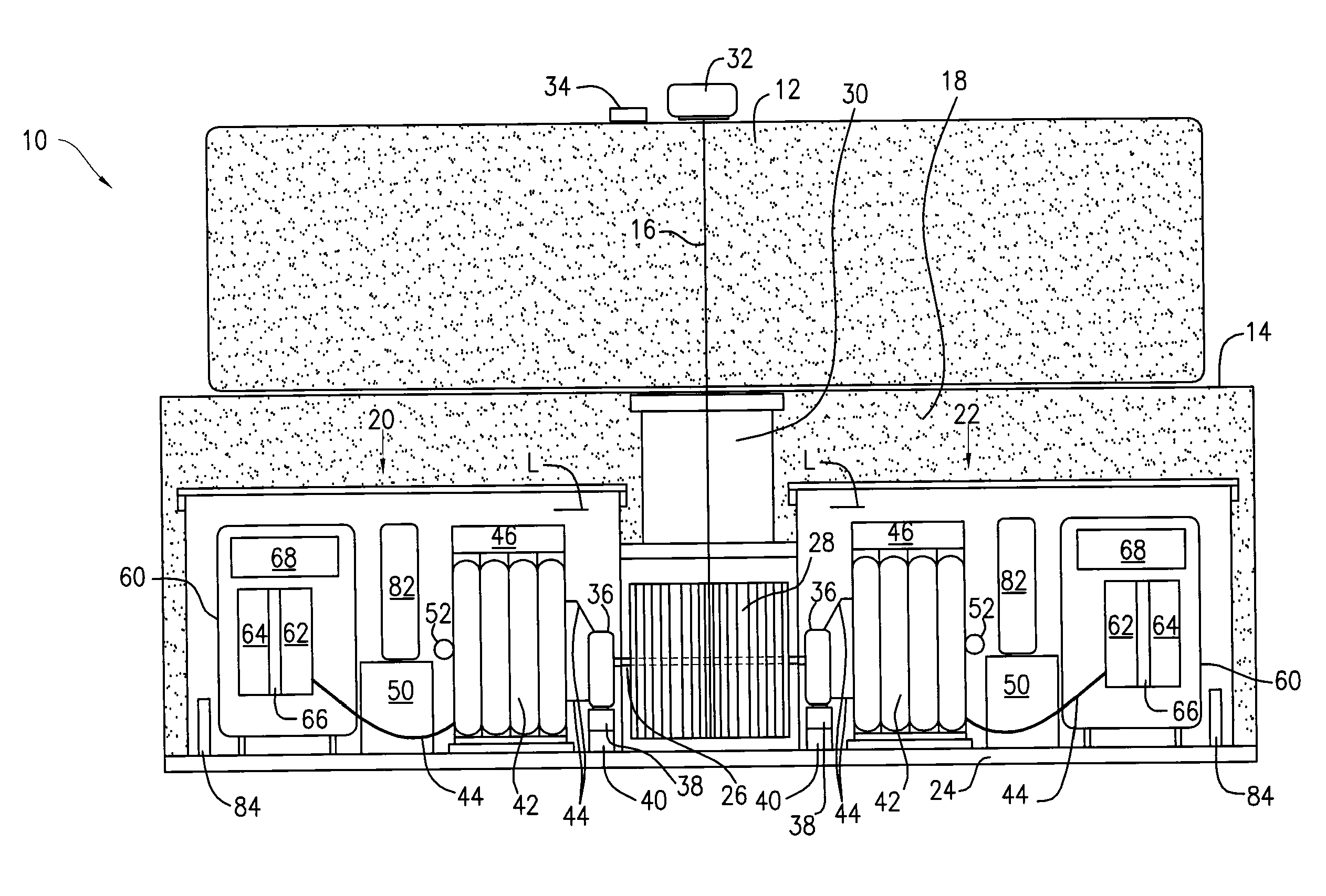
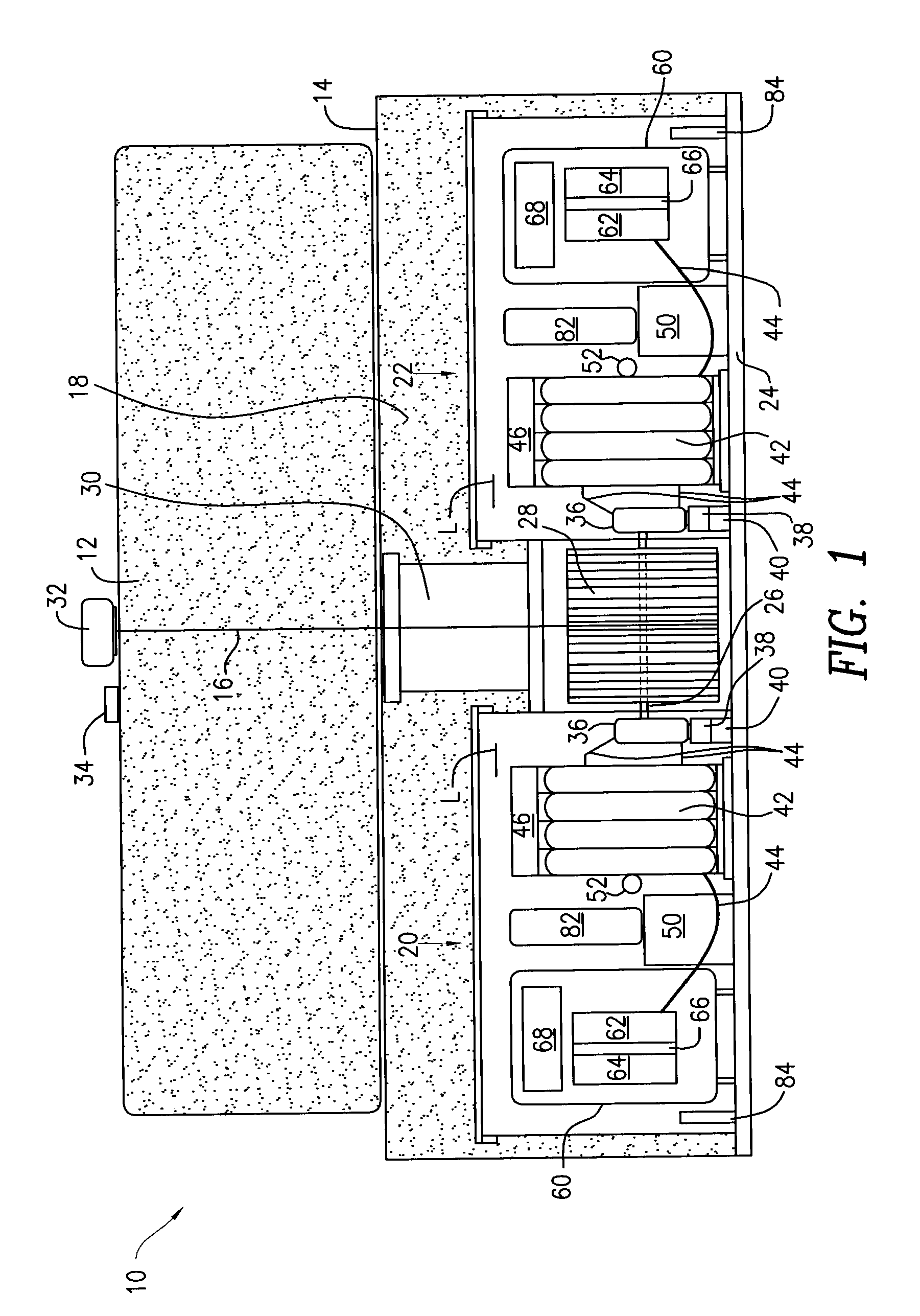
[0019]FIG. 1 illustrates a wave energy harnessing device (referred to herein as “the device”) 10 constructed in accordance with an exemplary embodiment of the present invention. The device 10 is adapted for deployment in a body of water, such as a sea or lake, for the purpose of extracting energy stored in the waves on the surface of the water and converting the extracted energy into electrical energy. The device 10 features novel functionality for optimizing the output of the energy extracted from the waves.

[0020]More particularly, the device 10 has a water surface flotation element (i.e., a “float”) 12 that is tethered to a housing 14 by a line 16. The float 12 has a foam-filled core with foam or other suitable material, and is cylindrically shaped with a flat top for ease of maintenance, although any other suitable shape may be used. The housing 14 includes a foam filled section 18 which has two fluid-tight compartments 20, 22 that are positioned within at opposite ends of the ho...


PUM


Abstract

A hydrokinetic device having a water surface float tethered to a submerged buoyant housing is provided with mechanisms for optimizing the amount of wave energy extracted from the waves by the device. Based on wave conditions, the optimization functionalities include controlling the depth of the housing to produce wave shoaling or storm avoidance, as well as to perform continuous phase control and load control for the purpose of matching the response frequency of the device to the frequency of the incident waves.

Description

CROSS-REFERENCE TO RELATED APPLICATIONS[0001]The present application claims the benefit of U.S. Provisional Patent Application Ser. No. 61 / 033,930, filed Mar. 5, 2008, the disclosure of which is incorporated herein by reference in its entirety, and is a continuation-in-part of prior U.S. patent application Ser. No. 12 / 042,845, filed on Mar. 5, 2008, which claims the benefit of U.S. Provisional Patent Application Ser. No. 60 / 906,148, filed Mar. 9, 2007, the disclosures of which are incorporated herein by reference in their entirety.FIELD OF THE INVENTION[0002]The present invention relates to a system for optimizing energy extraction output for hydrokinetic devices, and more particularly, to a system for optimizing energy extraction output for wave energy harnessing devices.BACKGROUND OF THE INVENTION[0003]The finite supply and environmental issues associated with fossil fuels have resulted in the need for alternate energy sources. The decline in fossil fuel sources, difficulty in obt...

Claims


Application Information

Patent Timeline
IPC IPC(8): F03B15/00F03B13/14
CPCF03B13/1885Y02E10/38F05B2240/40Y02E10/30
Inventor RAFTERY, MICHAEL WILLIAM
Owner STEVENS INSTITUTE OF TECHNOLOGY
Why Eureka
Try Eureka