
Ocean wave energy converter with multiple capture modes

a technology of ocean wave energy converter and capture mode, which is applied in the direction of electric generator control, machines/engines, mechanical equipment, etc., can solve the problems of low wave energy capture efficiency, and high cost per average unit of energy capture in the initial design, etc., and achieve the effect of highly dependent on wave length and capture efficiency

Inactive Publication Date: 2013-12-10
ROHRER TECH
View PDF34 Cites 19 Cited by
  • Summary
  • Abstract
  • Description
  • Claims
  • Application Information

AI Technical Summary

Benefits of technology

This approach significantly increases wave energy capture efficiency, allows for adjustable depth to optimize energy recovery in varying sea-states, and reduces moving mass, enabling the capture of both short wave lengths and long swells, resulting in higher power output while ensuring survivability in severe sea conditions.

Problems solved by technology

Less than a dozen OWEC designs are currently ocean deployed as “commercial proto-types.” Virtually all of these initial designs suffer from high cost per average unit of energy capture.
This is primarily due to the use of heavy steel construction necessary for severe sea-state survivability combined with (and in part causing) low wave energy capture efficiency.
Most subsurface OWECs are, unfortunately, designed for near shore sea bed deployment.
Ocean waves lose substantial energy as they approach shore (due to breaking or reflected waves and bottom hydrodynamic friction effects).
Near shore submerged sea bed located OWECs must be deployed at greater depths relative to average wave trough depths due to severe sea-state considerations to avoid breaking wave turbulence, and depth can not be adjusted for the large tidal depth variations found at the higher latitudes where average annual wave heights are greatest.
None of the prior art gas filled deformable containers use surface direct or low pressure indirect venting or breathing of container gas to increase container deformation or stroke and, therefore, wave energy capture.
None of these prior art subsurface OWECs enhance or supplement energy capture with overhead floating bodies.
All of the prior subsurface deformable container OWECs suffer from high mass (and therefore cost) and low energy capture efficiency (even more cost) usually due to either near shore and / or sea bed deployment and high moving mass.

Method used


Image

  • Ocean wave energy converter with multiple capture modes
  • Ocean wave energy converter with multiple capture modes
  • Ocean wave energy converter with multiple capture modes

Examples


Embodiment Construction

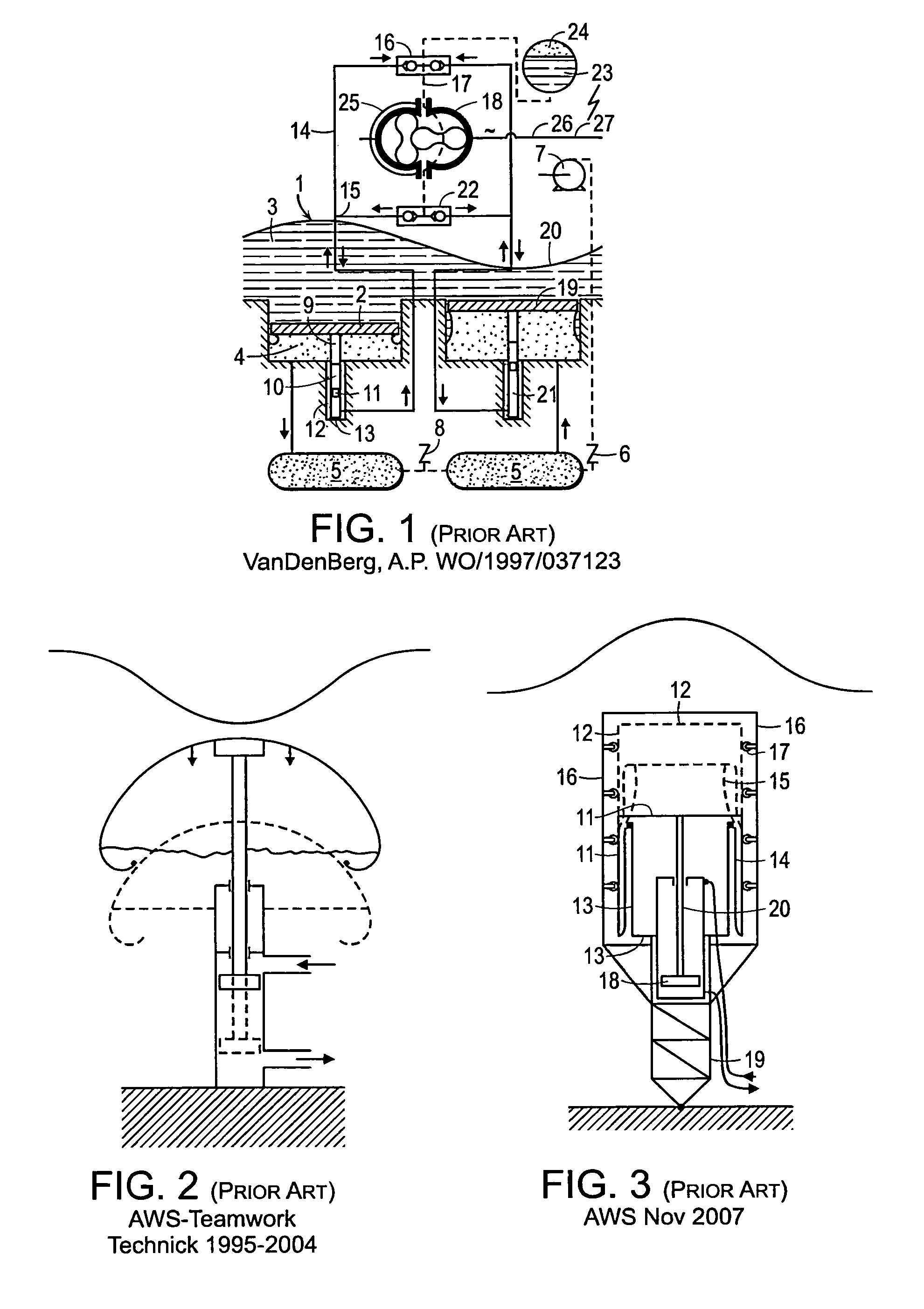
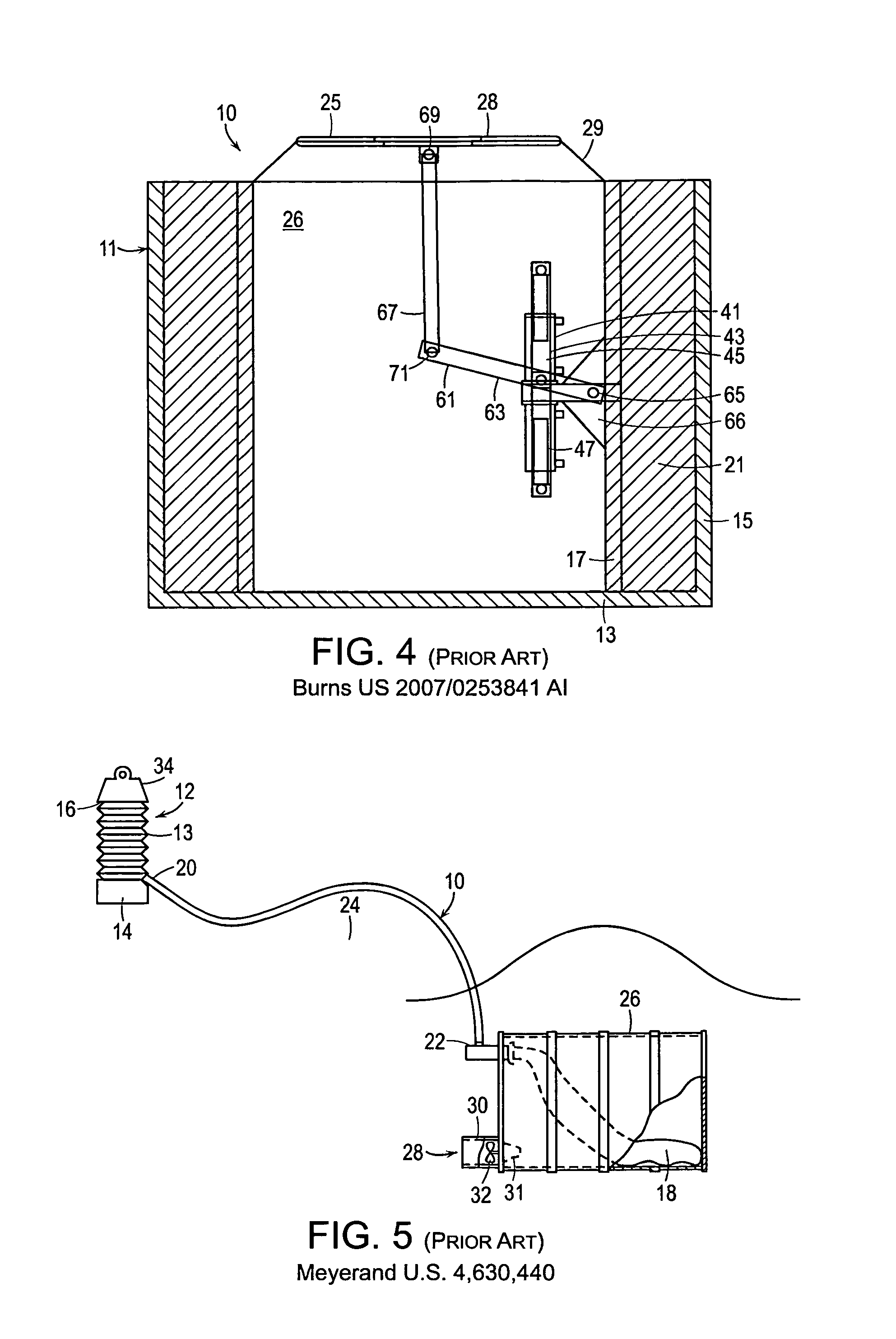
[0032]FIGS. 1-6 show prior art previously discussed and referenced. While most Figures of embodiments of the present invention show side elevational views which do not indicate the horizontal width (parallel to oncoming wave fronts) of the vessels of the subject invention, the width in preferred embodiments is elongated and exceeds vessel height and depth as is clearly shown in FIGS. 9b, 13b, and 14 of the present invention.

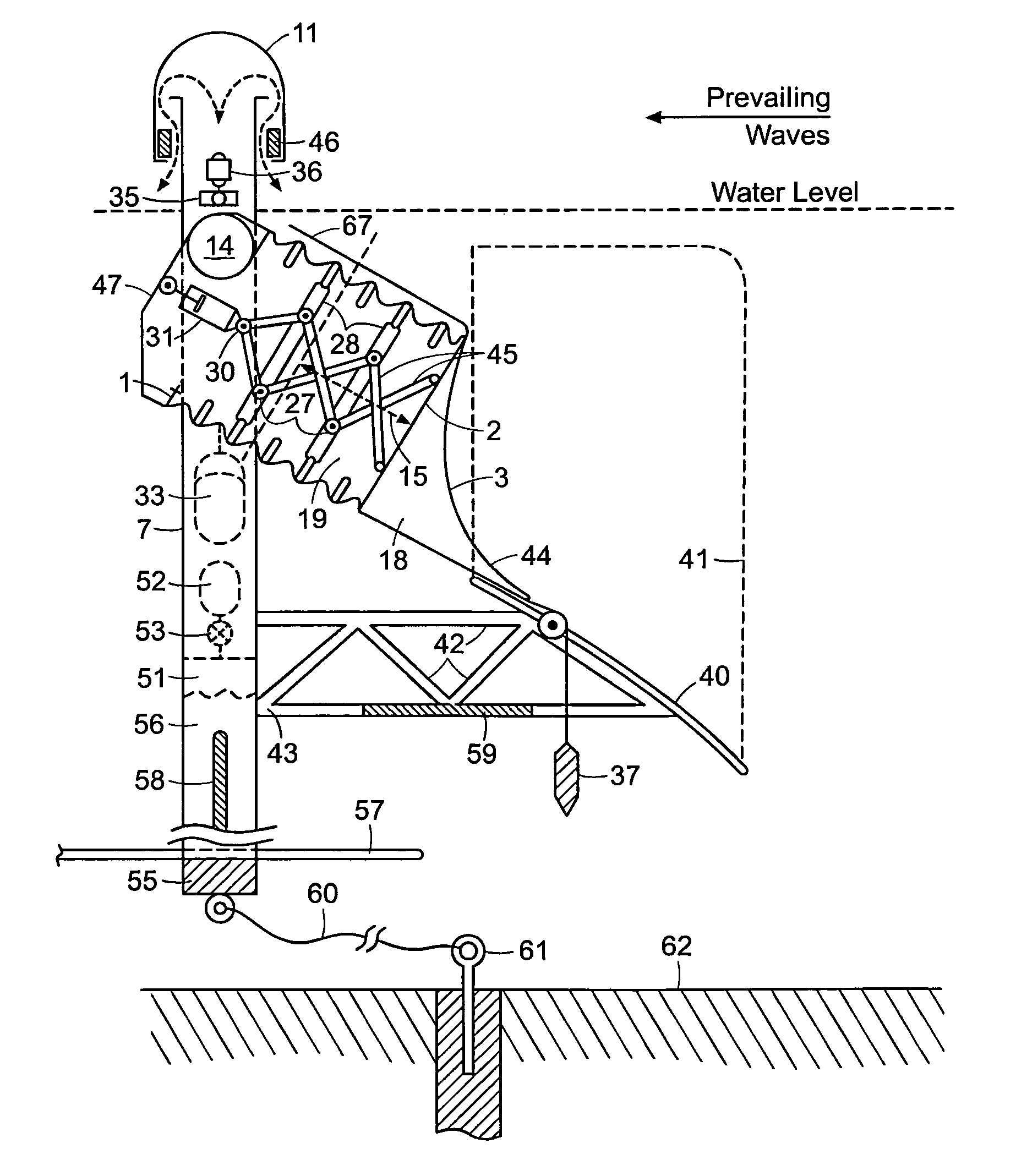
[0033]FIG. 7 shows an embodiment of the present invention with said first rearward fixed rigid surface 1 and said second movable surface 2 attached to or integral with a bladder 6 forming a substantially submerged (below mean water level 8) air filled container 19. Tracks 4 external to said bladder 6 restrict motion of movable surface 2 with tracking wheels 5 along said down sloping directional axis of movement 9 oriented towards the prevailing wave direction. Frontal hydrodynamic surface 3 is rigidly attached to movable surface 2 by bracket or housing 18 which c...


PUM


Abstract

An ocean wave energy converter utilizes a substantially submerged elongated absorption barrier oriented parallel to oncoming wave fronts having one or more substantially submerged air or gas filled variable volume vessels located between a relatively fixed position rigid rearward surface and a moving rigid wave front facing surface. Said vessel(s) are compressed by oncoming overhead wave crests both by increased hydrostatic pressure and wave kinetic impact, thereby capturing both wave potential energy (hydrostatic or heave) and kinetic (impact or surge) energy. Vessel compression is resisted by hydraulic, pneumatic, mechanical or linear electric generation means. Vessel re-expansion, when wave troughs are overhead, utilize hydraulic, pneumatic, electric, and / or mechanical (gravity mass or spring) means. Wave energy capture is enhanced by venting vessel air or gas directly to and from atmosphere or low pressure surface expandable vessel(s), which venting may also drive pneumatic turbine-generators, and by oncoming wave shoaling and focusing means.

Description

RELATED U.S. APPLICATION DATA[0001]Continuation-in-Part of U.S. applications Ser. No. 12 / 454,984 filed on May 27, 2009, Ser. No. 12 / 800,981 filed on May 27, 2010, and Ser. No. 12 / 802,018 filed on May 27, 2010.FIELD OF INVENTION[0002]This invention relates to devices for producing electrical power, pressurized water or other useful work from surface waves on a water body.[0003]More particularly, this invention relates to wave energy converters wherein either all or a substantial portion of the energy captured or produced is from one or more substantially submerged devices relying on overhead wave induced subsurface differences in hydrostatic pressure and surge or pitch which expand and contract or otherwise deform or deflect one or more air or gas filled variable volume containers, thereby producing useful work with a pneumatic, hydraulic, mechanical or linear electric power take off means resisting such compression or expansion. Such expansion and contraction can be enhanced or supp...

Claims


Application Information

Patent Timeline
Patent Type & Authority Patents(United States)
IPC IPC(8): F03B13/10
CPCF03B13/1815F03B13/182F03B13/188F03B13/24F05B2240/13F05B2260/406Y02E10/38Y02E10/30
Inventor ROHRER, JOHN W.
Owner ROHRER TECH
Learn More