LED driving circuit and method

a driving circuit and led technology, applied in the direction of electric variable regulation, process and machine control, instruments, etc., can solve the problems of high power consumption, temperature disadvantageously affecting the lifetime of leds, efficiency and applications, and impairing the performance of led driving circuits

Inactive Publication Date: 2010-02-04
RICHTEK TECH
View PDF4 Cites 27 Cited by
  • Summary
  • Abstract
  • Description
  • Claims
  • Application Information

AI Technical Summary

Benefits of technology

[0008]Another object of the present invention is to provide a LED driving circuit with significantly improved power efficiency.
[0009]Still another object of the present invention is to provide a LED driving circuit for greatly reducing power consumption to improve thermal issue.
[0010]Yet another object of the present invention is to provide a LED driving circuit for precisely controlling the driving current.
[0011]In a LED driving circuit according to the present invention, a regulator provides an output voltage to a LED light source on a current path, a current source coupled to the LED light source precisely controls the driving current on the current path, and a controller coupled to the current source and regulator detects the voltage of the current source to generate a control signal for the regulator to regulate the output voltage. The regulator regulates the output voltage to maintain the voltage of the current source at a low level, and consequently, the output voltage is almost completely applied to the LED light source. Thus, not only is the power efficiency greatly increased and the power consumption significantly reduced, but also the thermal issue is improved. Moreover, as the power consumption decreases, the required total input power is reduced, and thereby the power capacity of the regulator is allowed to be reduced.

Problems solved by technology

However, high power consumption and high temperature disadvantageously affect the LED's lifetime, efficiency and applications. FIG. 1 shows a conventional LED driving circuit 10, which includes a voltage source Vboost coupled to a LED string 12 and a transistor T11 coupled between the LED string 12 and a resistor Rref1 for controlling the driving current I1 of the LED string 12.
It is well known both the transistor T11 and the resistor Rref1 consume much power and thereby impair the performance of the LED driving circuit 10.
However, it is extremely difficult to precisely control the resistance of a small resistor with existing technology.

Method used


Image

  • LED driving circuit and method
  • LED driving circuit and method
  • LED driving circuit and method

Examples


first embodiment

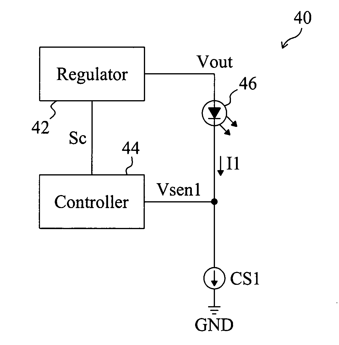
[0023]FIG. 5 shows a first embodiment according to the present invention. In a LED driving circuit 40, a regulator 42 provides an output voltage Vout to a LED light source 46 which may include an LED or a LED string, a current source CS1 is coupled to the LED light source 46 to control the driving current I1 of the LED light source 46, and a controller 44 detects the voltage Vsen1 of the current source CS1 to generate a control signal Sc, for the regulator 42 to regulate the output voltage Vout to maintain the voltage Vsen1 of the current source CS1 at a low level. The regulator 42 may be a switching buck converter, a switching boost converter or a switching buck-boost converter. The voltage Vsen1 of the current source CS1 is controlled as low as possible, for example at 0.2V, only if the current source CS1 could operate normally. Based on the detected voltage Vsen1, the controller 44 controls the regulator 42 to regulate the output voltage Vout and thereby maintain the output volta...

third embodiment

[0025]In the third embodiment shown FIG. 8, a LED driving circuit 70 includes a regulator 72 to provide output voltage Vout1, Vout2 and Vout3 to a red LED light source 76, a green LED light source 78 and a blue LED light source 80, respectively, current sources CS1, CS2 and CS3 are coupled to the LED light sources 76-80 to control the driving current I1, I2 and I3, respectively, and a controller 74 to detect the voltages Vsen1, Vsen2 and Vsen3 of the current sources CS1, CS2 and CS3 to generate a control signal Sc for the regulator 72 to regulate the output voltages Vout1, Vout2 and Vout3 to maintain the voltages Vsen1, Vsen2 and Vsen3 of the current sources CS1, CS2 and CS3 as low as possible, only if the current sources CS1, CS2 and CS3 could operate normally. In this embodiment, the output voltages Vout1, Vout2 and Vout3 are regulated according to the voltages Vsen1, Vsen2 and Vsen3, respectively. The regulator 72 may be a switching buck converter, a switching boost converter or ...


PUM


Abstract

A LED driving circuit includes a regulator to provide an output voltage to a LED light source, a current source to control the driving current of the LED light source, and a controller to detect the voltage of the current source to generate a control signal for the regulator to regulate the output voltage at a low level. There are no resistors on the current path established by the LED light source and current source, and the regulator may maintain the voltage of the current source as low as possible, thereby improving the power efficiency and reducing the power consumption.

Description

FIELD OF THE INVENTION[0001]The present invention is related generally to a light-emitting diode (LED) driving circuit and method and, more particularly, to efficiency improvement of a LED driving circuit.BACKGROUND OF THE INVENTION[0002]Recently, LEDs are extensively used as light sources in various applications. Since the brightness of LED is proportional to the driving current thereof, the LED driving circuit is required to well control the driving current. However, high power consumption and high temperature disadvantageously affect the LED's lifetime, efficiency and applications. FIG. 1 shows a conventional LED driving circuit 10, which includes a voltage source Vboost coupled to a LED string 12 and a transistor T11 coupled between the LED string 12 and a resistor Rref1 for controlling the driving current I1 of the LED string 12. The driving current I1 flows through the resistor Rref1 and thus produces a voltage Vsen1 thereacross, and the magnitude of the driving current I1 can...

Claims


Application Information

Patent Timeline
Patent Type & Authority Applications(United States)
IPC IPC(8): H05B41/36
CPCH05B33/0812Y02B20/345H05B33/0827H05B45/395H05B45/46Y02B20/30
Inventor LIU, KUO-CHI
Owner RICHTEK TECH
Why Eureka
Try Eureka