Persistent Current Switch

a technology of persistent current and switch, which is applied in the direction of superconducting magnets/coils, instruments, magnetic bodies, etc., can solve the problems of heating the refrigerator and injecting undesirable noise into the device, and achieve the effect of improving the design and operation method of persistent current switches

Active Publication Date: 2010-02-04
GLOBALFOUNDRIES US INC
View PDF8 Cites 62 Cited by
  • Summary
  • Abstract
  • Description
  • Claims
  • Application Information

AI Technical Summary

Benefits of technology

[0004]Principles of the invention provide an improved p

Problems solved by technology

Because the qubit is operated at temperatures near 20 milliKelvin (mK), the usual way of directly coupling

Method used


Image

  • Persistent Current Switch
  • Persistent Current Switch
  • Persistent Current Switch

Examples


Embodiment Construction

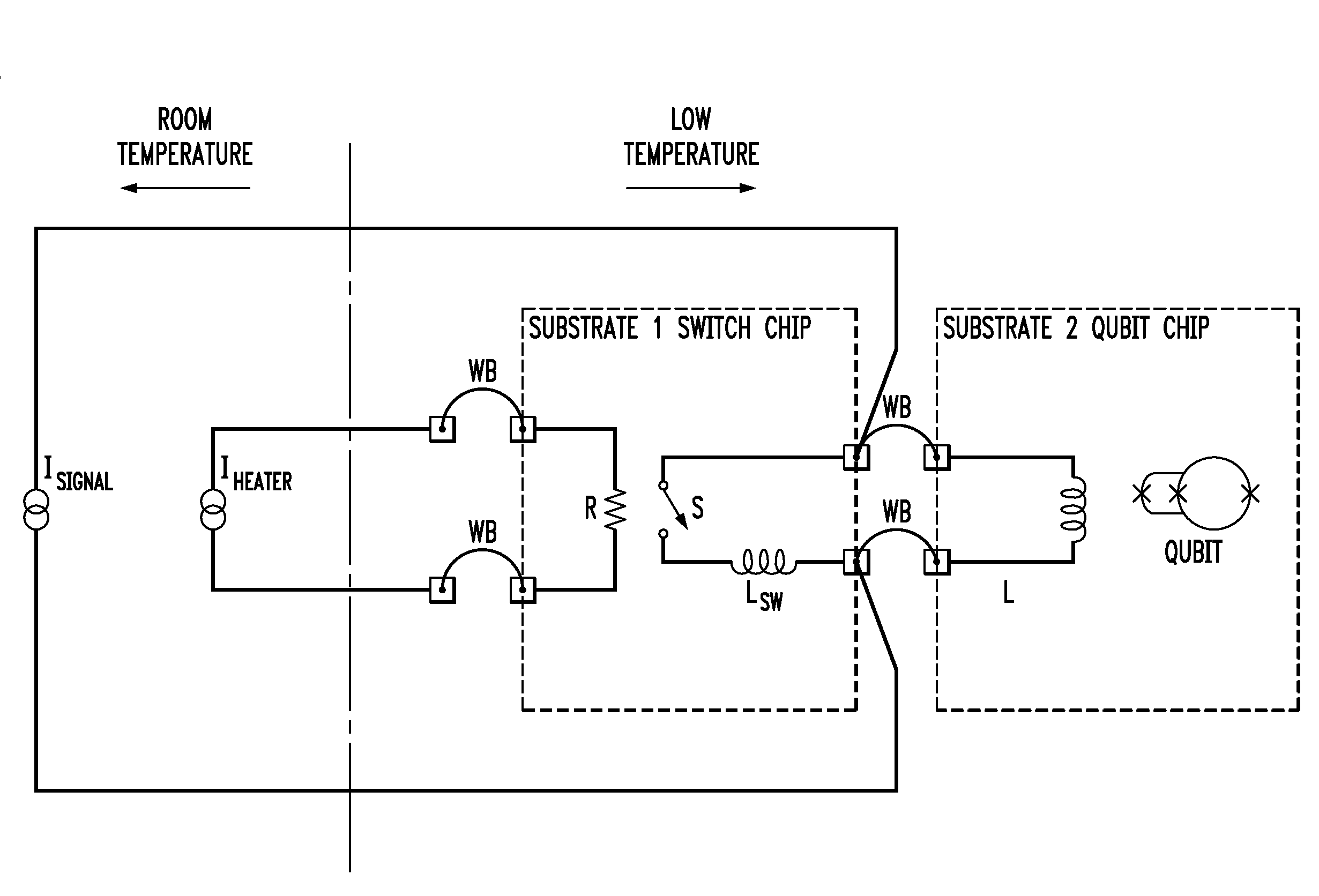
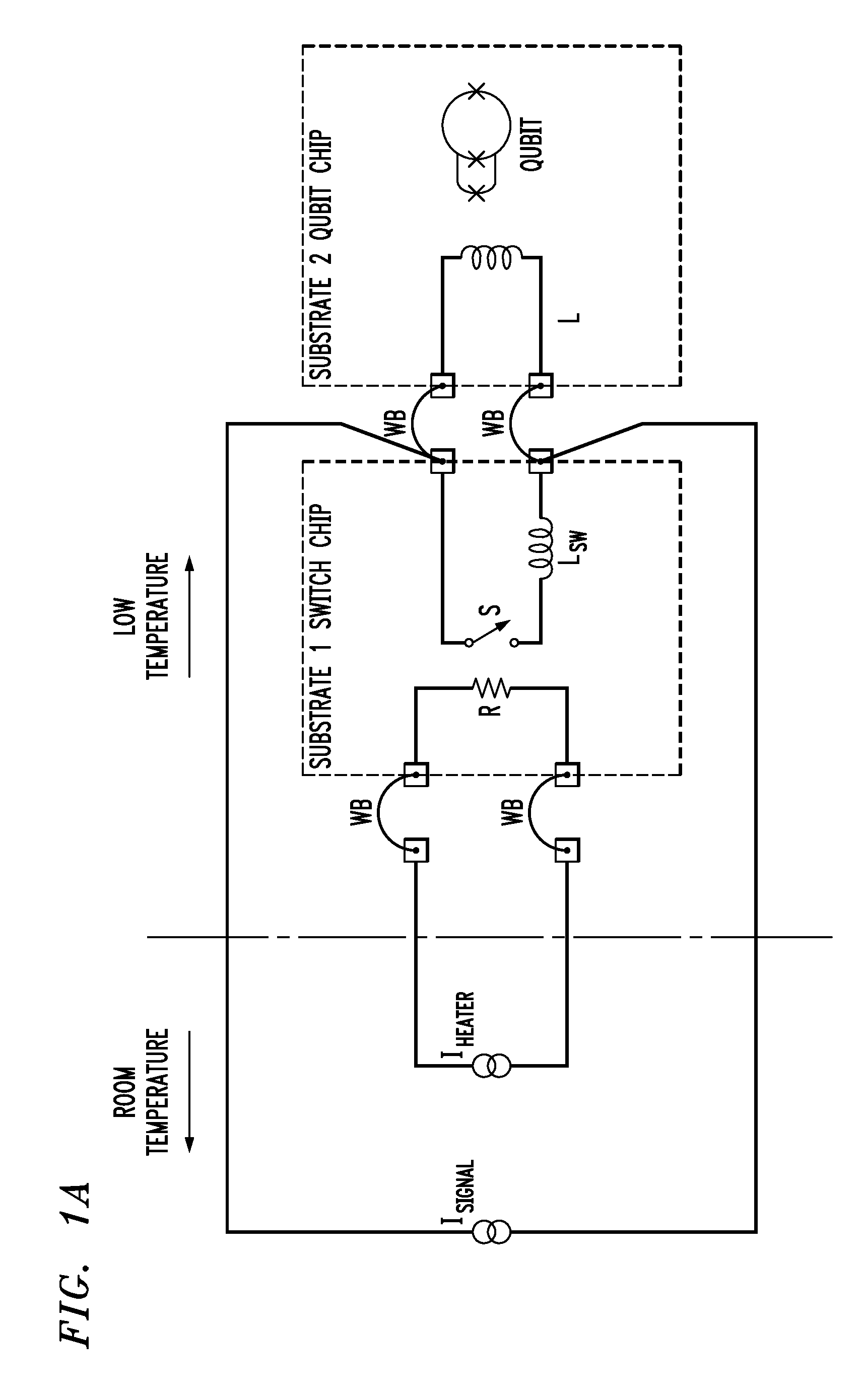
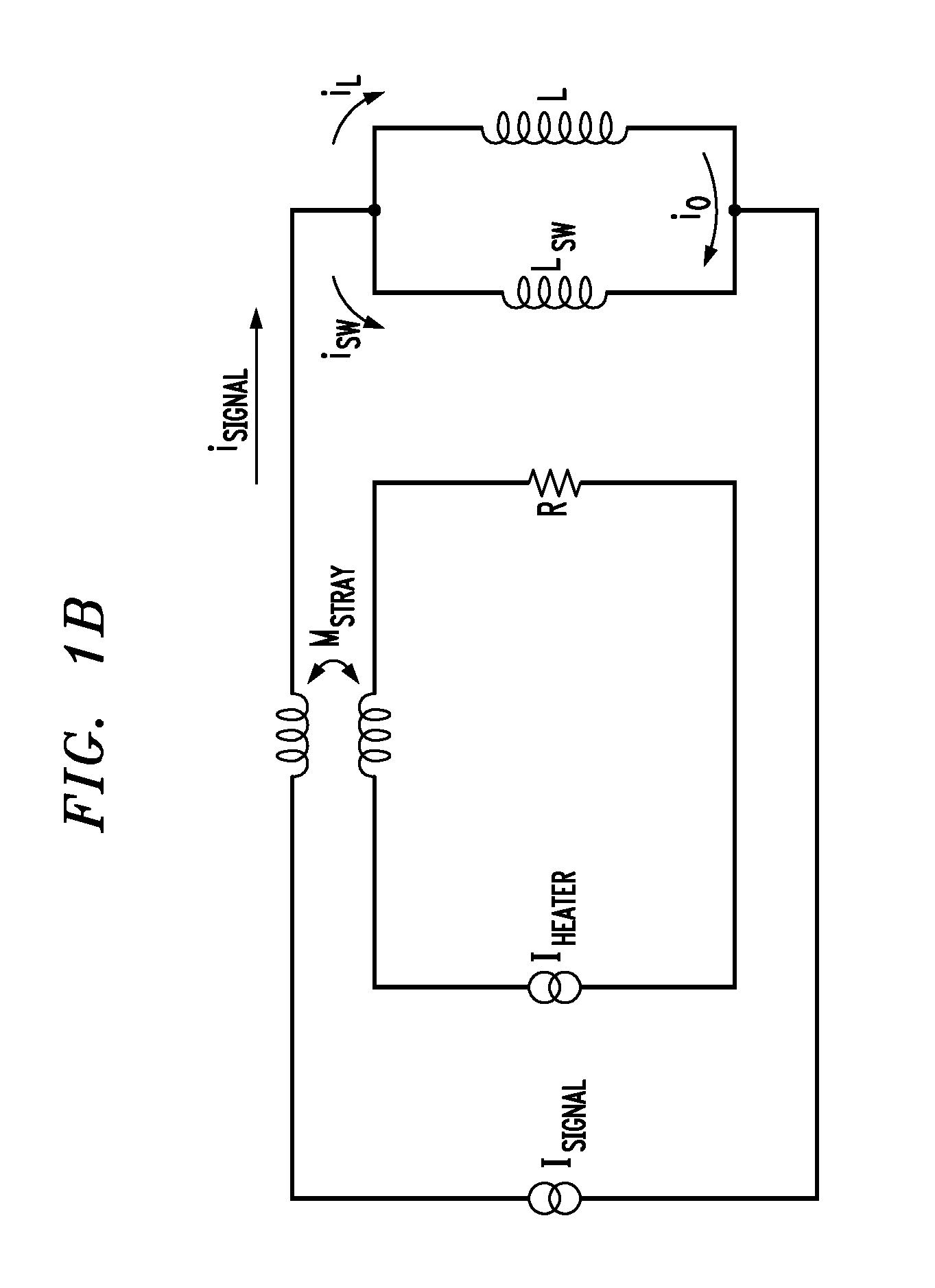
[0021]In accordance with illustrative principles of the present invention, it has been realized that, for qubit experiments, the standard switch design (as described above in the background section) has three undesirable features. First, the cooling power of most dilution refrigerators at 20 mK is typically less than 10 μW. Therefore, a switch that dissipates 50 μW of power will warm the refrigerator and the qubit if it is “on” or “open” for too long. Second, the inductance of the typical switch is too large in comparison to the inductance of the current bias control line that sets the qubit. In this case, a large fraction of the noise current from the room temperature control electronics is coupled to the qubit when the switch is “off.” Finally, the mutual inductance between the heater circuit and the persistent current switch is large and therefore this limits ones ability to set the control current accurately.

[0022]A persistent current switch design according to illustrative prin...


PUM


Abstract

An improved persistent current switch design and method of operation are disclosed. By way of example, a persistent current switch circuit comprises a heating element and a switch element located proximate to the heating element, the switch element being substantially formed from a material (by way of example only, titanium) which exhibits a superconducting temperature value below a superconducting temperature value exhibited by a material (by way of example only, aluminum) used to provide a connection to the switch element. The switch element is responsive to the heating element such that the heating element is used to control whether or not the switch element is in a superconducting state. The switch element may also have a folded geometry. Such persistent current switches exhibit low power and low inductance.

Description

FIELD OF THE INVENTION[0001]The present invention relates to thin film superconducting persistent current switches and, more particularly, to low power, low inductance thin film superconducting persistent current switches.BACKGROUND OF THE INVENTION[0002]It is known that quantum computation devices (also referred to as “qubits”) need high precision magnetic bias signals to accurately set the operating point of the device. Control currents on the order of 10 milliAmps (mA) are required, with an accuracy of one part in a million, and the noise temperature of the control electronics must be low to avoid decohering the qubit. Because the qubit is operated at temperatures near 20 milliKelvin (mK), the usual way of directly coupling control signals to the quantum bit will heat the refrigerator and inject undesirable noise into the device. The simplest way to solve these problems is to use a thin film superconducting persistent current switch. Examples of such persistent current switches a...

Claims


Application Information

Patent Timeline
IPC IPC(8): H01L39/16H02H7/00
CPCB82Y10/00H01L39/18G06N99/002G06N10/00H10N60/35
Inventor KEEFE, GEORGE A.KOCH, ROGER H.KOCH, INGAMILLIKEN, JR., FRANK P.ROZEN, JAMES R.
Owner GLOBALFOUNDRIES US INC
Why Eureka
Try Eureka