Image processing apparatus, method of controlling the same, computer program, and storage medium
a technology of image processing and control apparatus, which is applied in the direction of instruments, television systems, static indicating devices, etc., can solve the problems of display quality degradation and liquid crystal display apparatus not being able to smoothly play back motion pictures, so as to improve moving image quality, eliminate imbalance in dc components, and high image quality
- Summary
- Abstract
- Description
- Claims
- Application Information
AI Technical Summary
Benefits of technology
Problems solved by technology
Method used
Image
Examples
first embodiment
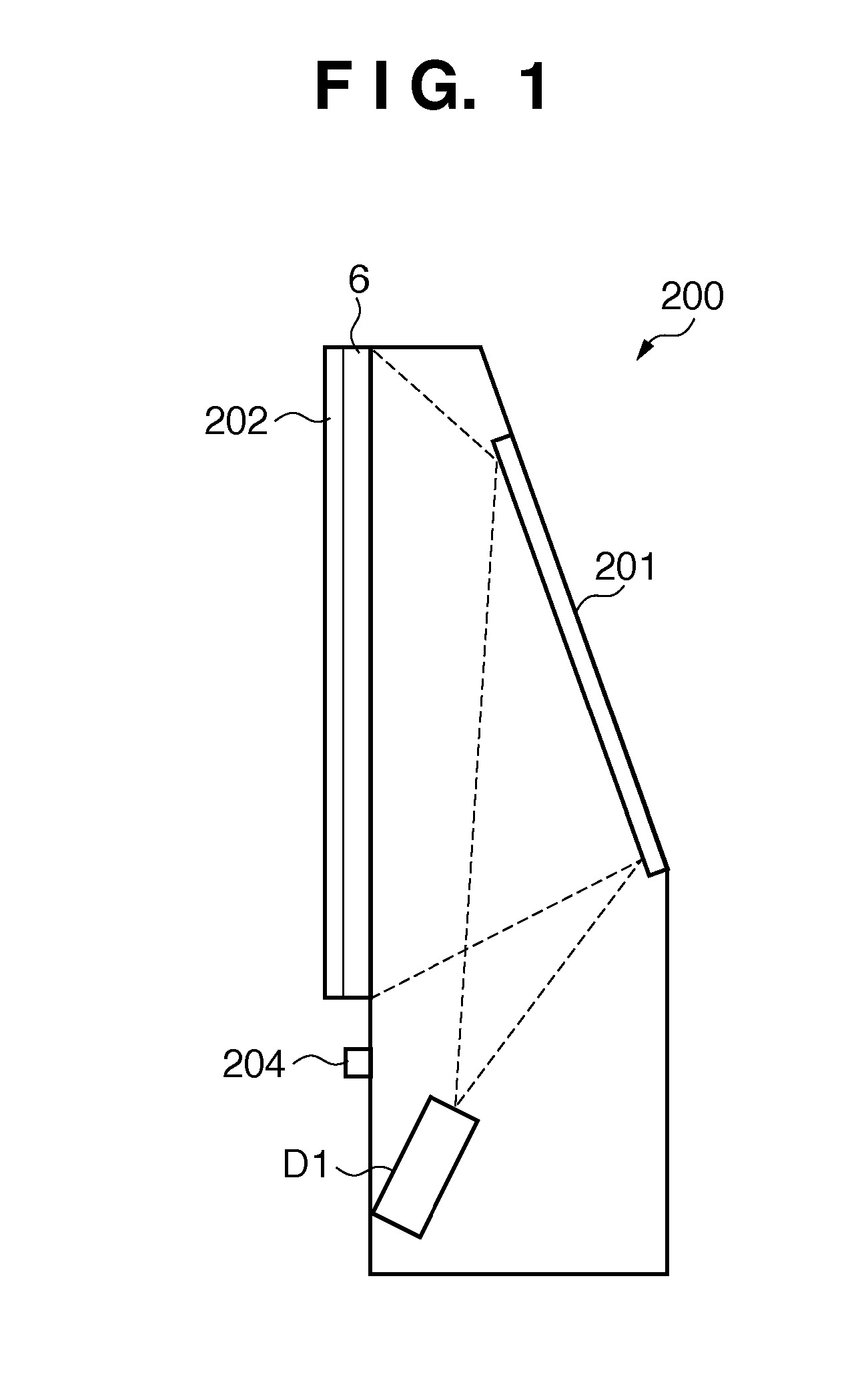
[0032]FIG. 1 is a side view showing an example of a rear projection type display apparatus 200 according to the first embodiment of the present invention.
[0033]Referring to FIG. 1, a moving image projected from a projection type display engine D1 is reflected by a reflection mirror 201 and projected to the rear side of a screen 6. The screen 6 has a digitizer 202 attached to its front panel. When a user indicates a point on the front panel of the screen 6 with the digitizer 202 using a digitizer pen (not shown), the coordinates of the indicated point are input to the display apparatus 200. Various kinds of digitizers such as those of an optical type, pressure-sensitive type, and ultrasonic type are usable as the digitizer. A brightness control switch 204 controls the brightness of an image to be displayed on the screen 6.
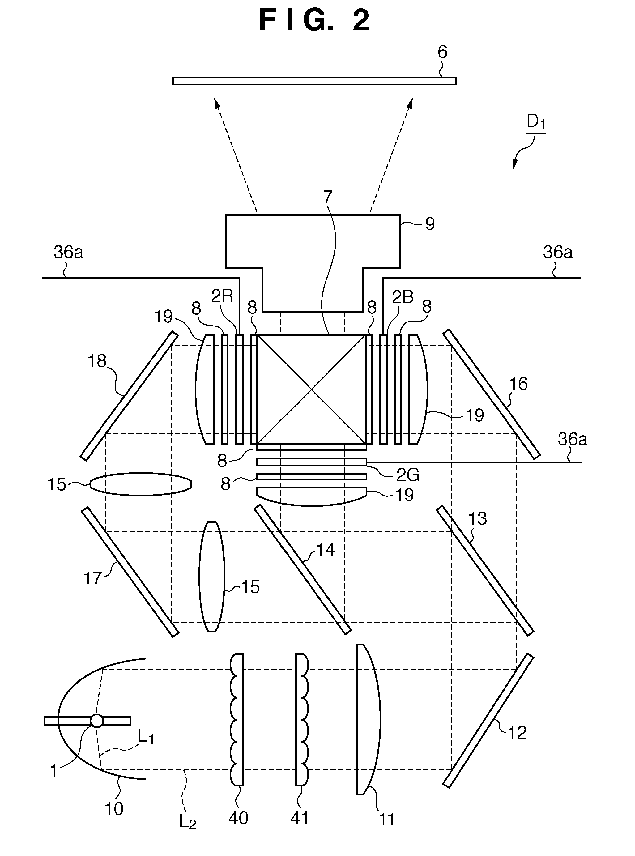
[0034]The structure of the projection type display engine D1 according to the first embodiment will be described next with reference to FIG. 2. Referring to FIG. 2,...
second embodiment
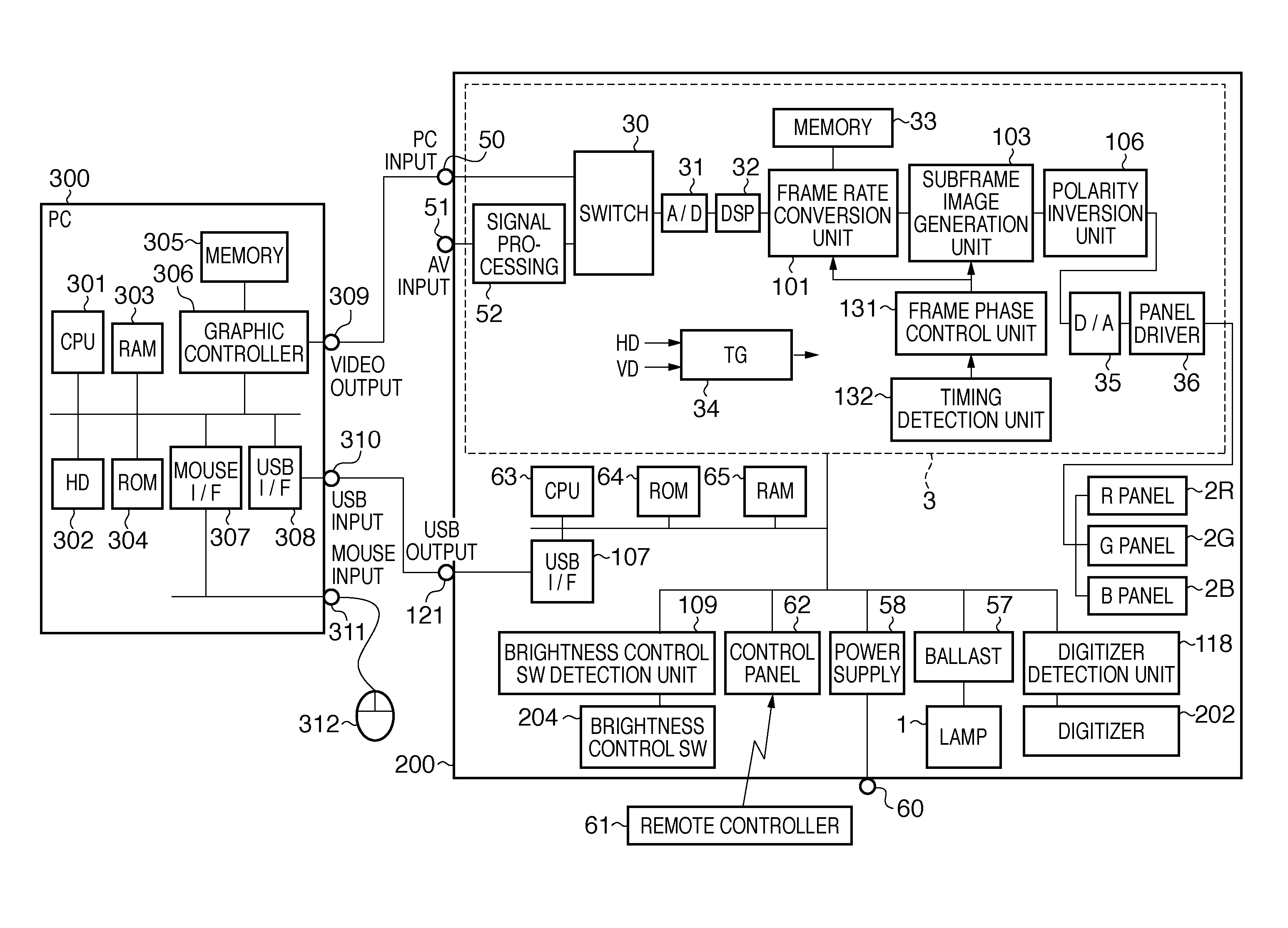
[0069]In the second embodiment of the present invention, the user operates a remote controller 61 to switch the input signal to a display apparatus 200. The frame phase is switched in accordance with the timing of input signal switching. The frame phase switching processing will be described with reference to FIG. 9. FIG. 9 is a flowchart illustrating an example of frame phase switching processing. As the input signal switching processing, for example, a case can be considered in which video 1 serving as the first input unit is switched to video 2 serving as the second input unit.
[0070]First, the user performs an input switching operation on the remote controller 61 serving as an input switching reception unit. In step S901, a control panel 62 receives a signal as a switching instruction transmitted from the remote controller 61 in accordance with the operation. The control panel 62 notifies a CPU 63 of reception of the signal from the remote controller 61. In accordance with the no...
third embodiment
[0075]The third embodiment of the present invention will be described next. In the third embodiment, a method of switching the display frame phase with respect to the phase of polarity inversion more often than in the above-described second embodiment will be explained.
[0076]FIG. 10 is a block diagram showing an example of a signal processing system according to the third embodiment. The arrangement in FIG. 10 is wherein a scene change detection unit 1101 is newly included after a frame rate conversion unit 101 in FIG. 3.
[0077]The scene change detection unit 1101 compares the average luminance value of a preceding frame image output from a memory 1102 with that of a current frame image output from the frame rate conversion unit 101 and determines based on the degree of change whether a scene change exists. In the third embodiment, the presence / absence of a scene change is determined by checking whether the average luminance value has changed by 50%.
[0078]Upon detecting a scene chang...
PUM
 Abstract
Description
Claims
Application Information
 - R&D
- Intellectual Property
- Life Sciences
- Materials
- Tech Scout
- Unparalleled Data Quality
- Higher Quality Content
- 60% Fewer Hallucinations
Browse by: Latest US Patents, China's latest patents, Technical Efficacy Thesaurus, Application Domain, Technology Topic, Popular Technical Reports.
© 2025 PatSnap. All rights reserved.Legal|Privacy policy|Modern Slavery Act Transparency Statement|Sitemap|About US| Contact US: help@patsnap.com


