
Multiplexing Imaging System for Area Coverage and Point Targets

Inactive Publication Date: 2010-02-04
ITT MFG ENTERPRISES LLC
View PDF25 Cites 34 Cited by
  • Summary
  • Abstract
  • Description
  • Claims
  • Application Information

AI Technical Summary

Problems solved by technology

Generally, when an overhead surveillance system tries to maximize spatial resolution, it does so at the expense of diminished area coverage.

Method used


Image

  • Multiplexing Imaging System for Area Coverage and Point Targets
  • Multiplexing Imaging System for Area Coverage and Point Targets
  • Multiplexing Imaging System for Area Coverage and Point Targets

Examples


Embodiment Construction

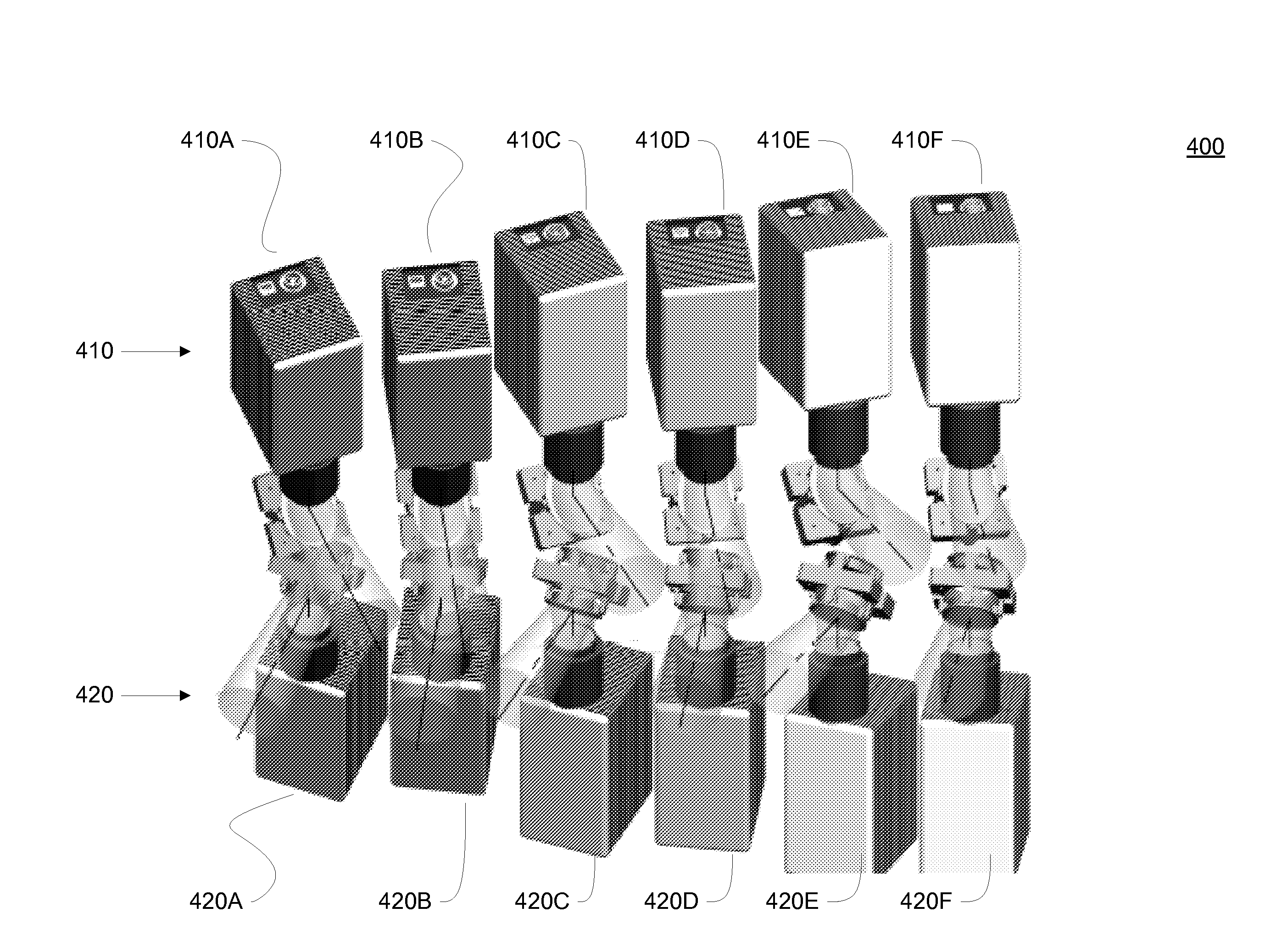
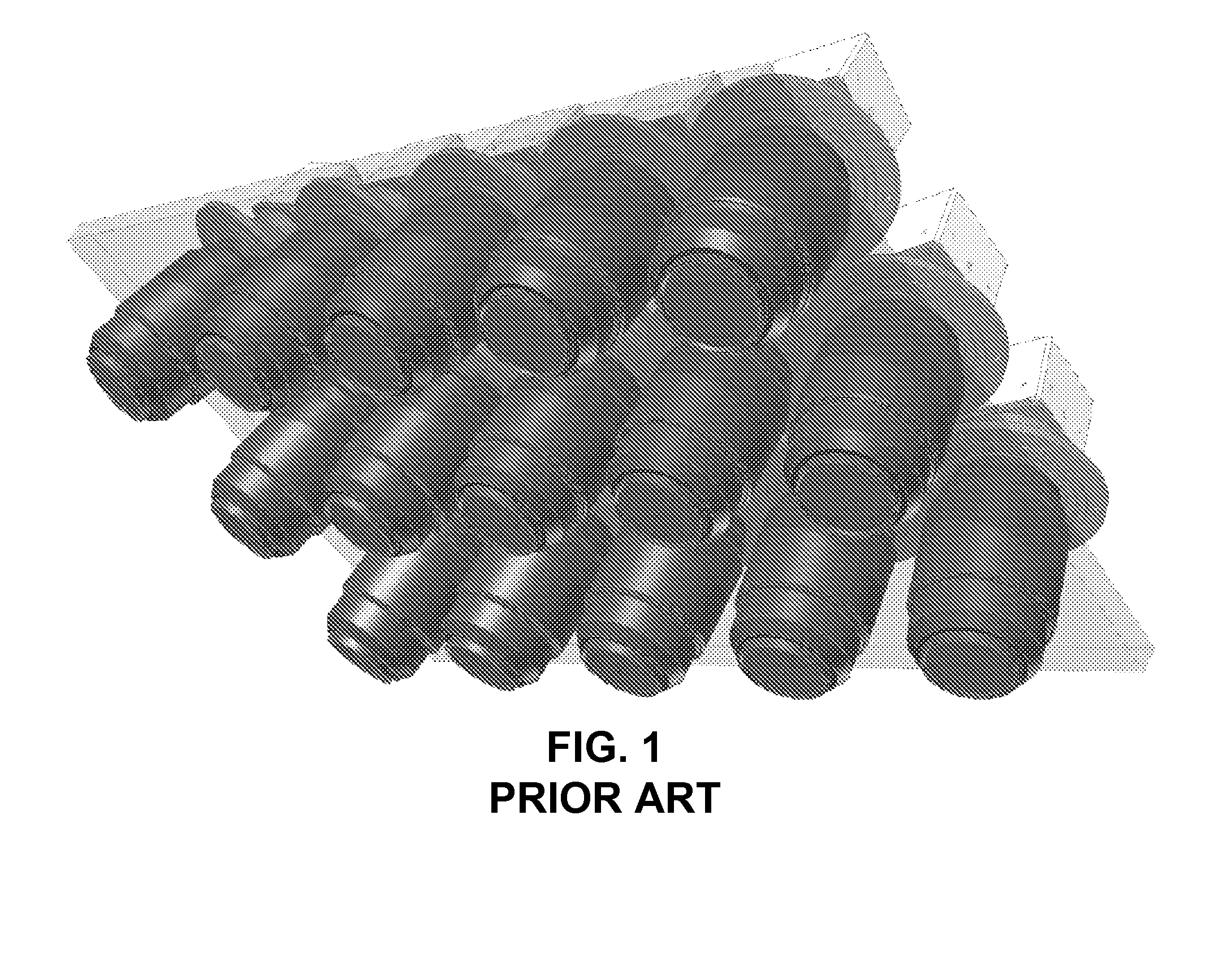
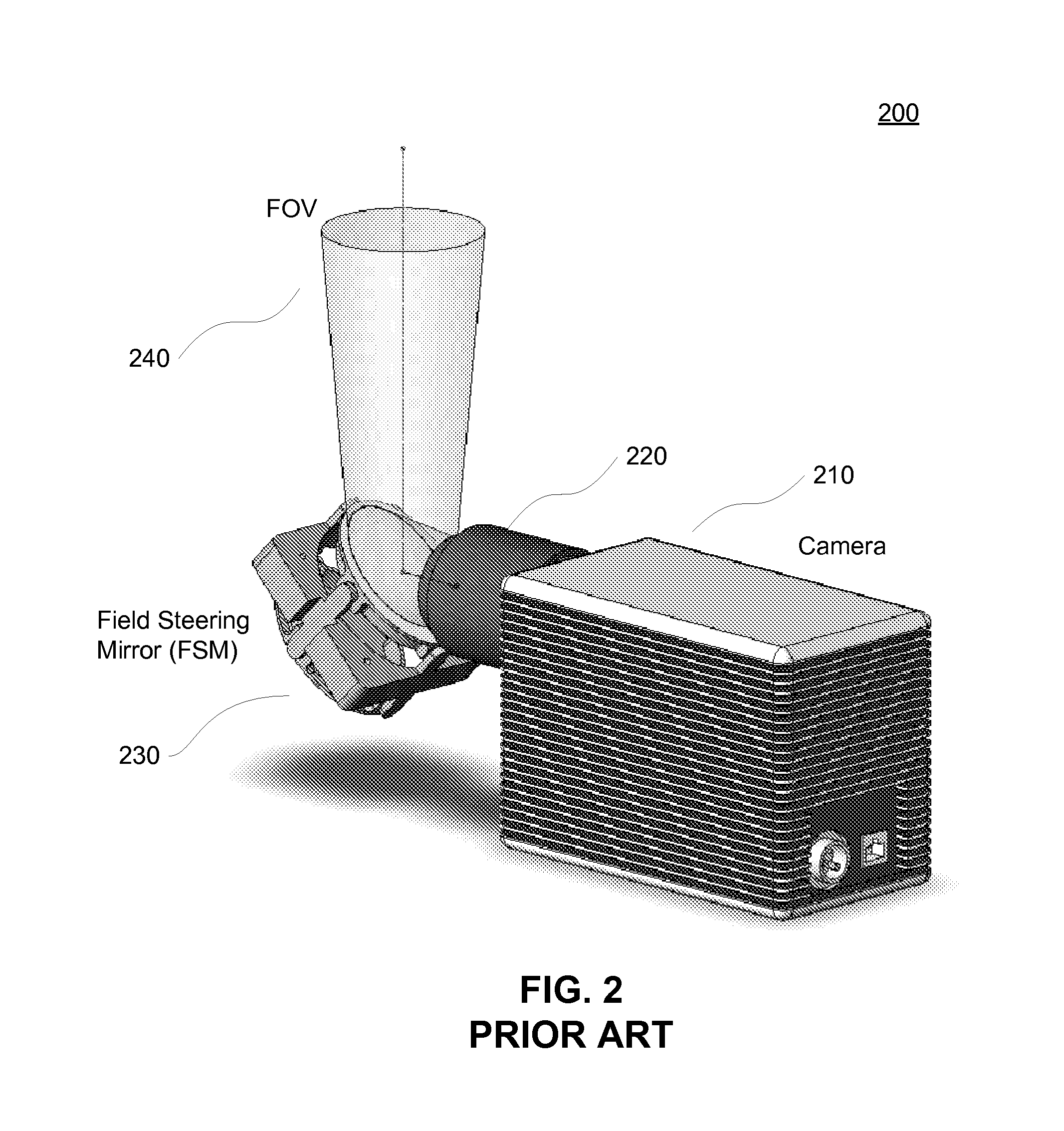
[0026]The conventional method of using a bank of cameras, as illustrated in FIG. 1, suffers from numerous disadvantages. In overhead surveillance, such as surveillance systems installed in unmanned aerial vehicles (“UAV”), manned aircraft, or satellites, payload volume and mass is constrained. Packaging a bank of cameras within these constraints is sometimes difficult to accomplish. Often, these constraints require using fewer cameras than optimal for achieving a desired field of view (“FOV”). The result is either a smaller FOV than desired or a reduced spatial resolution.

[0027]Power supply constraints also limit the number of cameras used in surveillance systems. Power available onboard satellites, UAVs, and manned aircraft is limited, and the power required by an optimal number of fixed cameras in a bank may exceed the available power. Thus, fewer than the optimal number of cameras may need to be used.

[0028]Cost is also a factor in constructing a bank of fixed cameras for overhead...


PUM


Abstract

A system for imaging a scene. The system includes a plurality of cameras, each camera including an image sensor and a field steering mirror. The system also includes a controller and a storage device. The controller is coupled to the cameras and the storage device and is configured to direct the field steering mirrors of the cameras to collect a plurality of image tiles of a scene. The is also configured to store the image tiles in the storage device with time stamps and location information.

Description

FIELD OF THE INVENTION[0001]The present invention generally relates to image processing and, more specifically, to controlling a bank of cameras having field steering mirrors for capturing a plurality of image tiles of a scene and mosaicking such tiles into a composite image.BACKGROUND OF THE INVENTION[0002]Generally, when an overhead surveillance system tries to maximize spatial resolution, it does so at the expense of diminished area coverage. The opposite is also true: Maximizing area coverage is done at the expense of diminished spatial resolution. Various techniques attempt to maximize spatial resolution for a given area coverage.[0003]A camera having a sensor with a fixed array size (M×N) of pixels may capture more area by reducing its focal length. The focal length may be reduced by “zooming out,” i.e., increasing the angular field-of-view (herein “FOV”) of the camera. This may be seen when the camera “pans back.” Since the number of pixels in the camera is a constant M×N arr...

Claims


Application Information

Patent Timeline
IPC IPC(8): H04N5/225H04N5/76
CPCH04N7/181G06F16/45
Inventor HAHM, TIMOTHY PAULTANTALO, THEODORE ANTHONYBROWER, BERNARD V.
Owner ITT MFG ENTERPRISES LLC
Learn More