Moving object recognizing apparatus

a recognition apparatus and moving object technology, applied in the field of moving object recognition apparatus, can solve the problems of deteriorating recognition ratio of moving objects, inability to calculate precision optical flow, and inability to obtain optical flow precision, etc., and achieve the effect of improving safety and low recognizability

Inactive Publication Date: 2010-02-04
AISIN SEIKI KK
View PDF9 Cites 37 Cited by
  • Summary
  • Abstract
  • Description
  • Claims
  • Application Information

AI Technical Summary

Benefits of technology

[0040]If the convergence to the vanishing point or the discrepancy in the external ratio of the optical flow is quantified as deviation relative to each grouping criteria or as dispersion of this deviation, it becomes possible for the reliability calculation unit to effectively show the reliability of image processing involved in the moving object recognition.
[0044]For calculation of optical flows with good precision, it is important to extract the point feature, as the recognition target pattern, from the image data with accuracy. Compared with its surrounding image, the point feature has a characteristic property (uniqueness) such as increased luminance. Needless to say, this characteristic property is affected also by the quality of this image data. Therefore, in extracting the point feature, there is calculated a point feature amount which is a quantitative representation of the characteristic property. If the point feature amount is small, this means that the point feature has a low or weak characteristic property, so that there is greater possibility of confusion with other point features. As described above, since the recognition reliability is calculated based upon the result of at least one of image processing operations, the moving object recognizing apparatus can calculate the recognition reliability with using the point feature reliability indicative of the reliability of the point feature.
[0051]According to the above-described construction, the recognition reliability is calculated with temporal continuity, based upon the result of the latest image processing operation and the result of the previous image processing operation. Therefore, the reliability calculation unit can calculate the recognition reliability with precision, with suppressing adverse effect from accidental image data disturbance.
[0063]A same single moving object does not change much in its velocity or position. Therefore, with use of the continuity reliability indicative of the certainty of a same moving object being recognized, the reliability calculation unit can effectively calculate the recognition reliability.
[0065]With this construction, there is provided a moving object recognizing apparatus which is capable of effectively reporting the result of recognition of the moving object and capable also of enabling reporting in an appropriate manner when needed.
[0071]With the above construction, the reporting unit can effect the reporting in an appropriate manner according to the need, i.e. in the alarm mode or caution mode. Further, in the case of very low recognition reliability such as when the recognition reliability is below the second threshold value, the reporting unit does not effect the reporting at all. Therefore, such inconvenience as the moving object recognizing apparatus issues an alarm even in the absence of any approaching moving object. Further, in case the recognition reliability is relative low as being under the first threshold value, the reporting is made in the caution mode with lower recognizability than the alarm mode. Therefore, the safety can be improved.

Problems solved by technology

As such, depending on the surrounding situation such as weather, location, time of day, etc., the optical flows cannot sometimes be obtained with precision, due to such factors as low image contrast.
In such case, calculation of precision optical flow may prove impossible.
When the calculation of optical flow is inaccurate, the recognition ratio of the moving object too is deteriorated.
As a result, the moving object recognizing system may become unable to issue an alarm even in the event of approaching of another vehicle or may issue an alarm erroneously in the event of absence of any approaching vehicle.
Especially, if the moving object recognizing system has issued such “false” alarms frequently in the absence of any approaching vehicle, the driver may become distrustful of this moving object recognizing system.
As a result, in the event of issuance of “correct” alarm, the driver may neglect this or may stop using the system at all, so that there occurs deterioration in the safety.

Method used


Image

  • Moving object recognizing apparatus
  • Moving object recognizing apparatus
  • Moving object recognizing apparatus

Examples


Embodiment Construction

[0090]Next, an embodiment of the present invention will be described with reference to the drawings. Here, there will be described an example wherein the moving object recognizing apparatus of the invention is provided for use in a vehicle (self vehicle) for recognizing another vehicle approaching the self-vehicle.

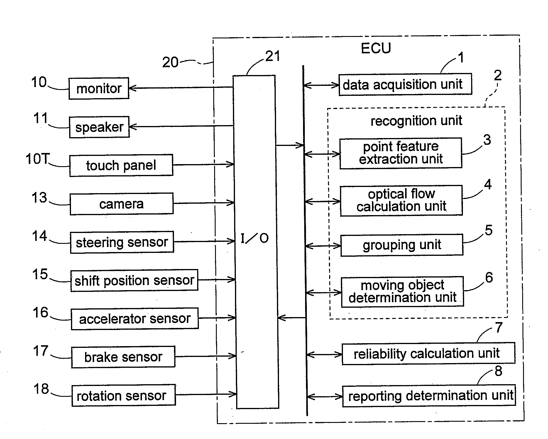
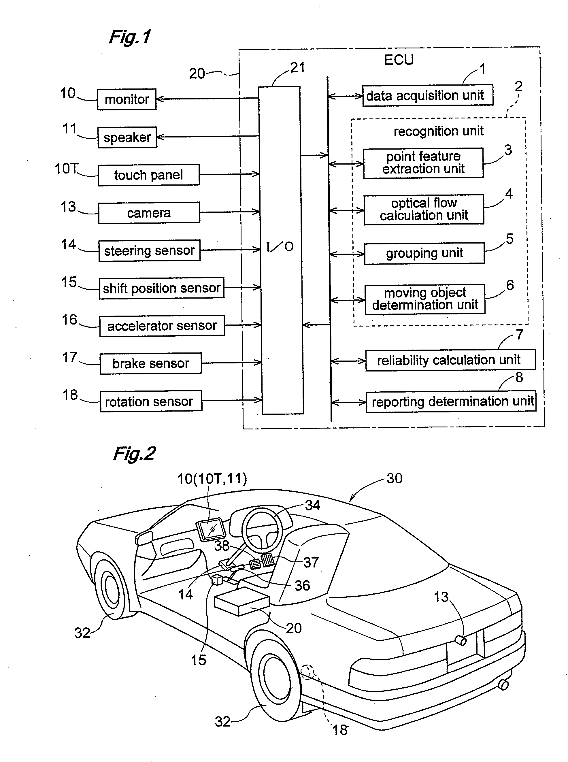
[0091]FIG. 1 is a block diagram schematically showing the logic construction of a moving object recognizing apparatus according to the present invention. And, FIG. 2 is a perspective view showing a driver's seat made visible by cutting out a portion of a vehicle.

[0092]The moving object recognizing apparatus of the present invention comprises an ECU (electronic control unit) 20 as a core component thereof as shown in FIG. 2 and is mounted on a vehicle 30. The ECU 20, as shown in FIG. 1, includes an input / output interface 21 for inputting / outputting information and a microprocessor for processing information from this input / output interface 21. Needless to say, a portion or ...


PUM


Abstract

Provided is a moving object recognizing apparatus capable of effectively showing reliability of result of image processing involved in moving object recognition and issuing alarms in an appropriate manner when needed. The moving object recognizing apparatus includes a data acquisition unit (1) for acquiring image data obtained in time series by an imaging device, a recognition unit (2) for recognizing a moving object by executing a plurality of image processing operations on two of the image data obtained at different times, the plurality of image processing operations including an operation of calculating correlativity of a same recognition target pattern, and a reliability calculation unit (7) for calculating recognition reliability indicative of reliability of recognition of the moving object, based upon at least one of the results of the respective image processing operations by the recognition unit (2).

Description

TECHNICAL FIELD[0001]The present invention relates to a moving object recognizing apparatus for recognizing a moving object from image data.BACKGROUND ART[0002]In recent years, a variety of techniques have been proposed for improving safety in vehicle driving. As one such method, there has been proposed a moving object recognizing apparatus for recognizing, as a moving object, a vehicle approaching a self vehicle, recognizing in particular, another vehicle approaching from behind the self vehicle as a moving object. As shown below, Patent Documents 1-3 show the techniques relating to such moving object recognition.[0003]Patent Document 1 (JP6-130076A) discloses a method for detecting a vehicle traveling obliquely reward of a self vehicle. In this method, the vehicle traveling obliquely rearward is detected based upon an optical flow derived from captured images and a further optical flow corresponding to a traveling velocity of the self vehicle obtained by a vehicle speed sensor. Mo...

Claims


Application Information

Patent Timeline
Patent Type & Authority Applications(United States)
IPC IPC(8): G06K9/00
CPCG06T7/2066G06T7/269
Inventor AKITA, TOKIHIKO
Owner AISIN SEIKI KK
Why Eureka
Try Eureka