Fan filter unit

a filter unit and fan technology, applied in the direction of positive displacement liquid engines, lighting and heating apparatus, heating types, etc., can solve the problems of inability to adjust the rotating speed of the motor, poor capability, and whining sound, so as to suppress the whining sound

Inactive Publication Date: 2010-02-04
PANASONIC CORP
View PDF3 Cites 18 Cited by
  • Summary
  • Abstract
  • Description
  • Claims
  • Application Information

AI Technical Summary

Benefits of technology

[0006]The present invention solves the conventional disadvantage as described above. It is an objective of the present invention to provide a fan filter unit that can cope with the variation in capabilities of motors of a fan filter unit to suppress the whining sound. The fan filter unit of the present invention has a plurality of fan motors, a plurality of detectors, a total controller, and a filter. Each of the fan motors includes a fan and a motor. Each of the detectors detect a rotating speed of each of the motors. The total controller subjects, based on rotating speeds detected by the detectors, the respective fan motors to a feedback control by which the detected rotating speeds are identical with a set rotating speed. When a rotating speed value detected by any of the detectors is smaller than a rotating speed value detected by the other detector, the total controller performs a tuning control of the rotating speeds so that the rotating speed of the other fan motor is adjusted to the slower rotating speed of the fan motor. According to the present invention, in a fan filter unit having a plurality of fan motors, the rotating speed of the respective fan motors including variation in the motor capability can be identical. Even when the rotating speeds of the fan motors change due to variation in air pressure in a place holding the fan motors, the fan filter unit can allow the rotating speeds to be identical so as to suppress the whining sound.

Problems solved by technology

The use of a plurality of fan motors, however, may cause a whining sound.
However, this adjustment of motor rotating speeds may be prevented from being achieved when variation in capabilities of a plurality of motors causes a later motor to have a capability inferior to that of a former motor.

Method used


Image

  • Fan filter unit
  • Fan filter unit
  • Fan filter unit

Examples


first exemplary embodiment

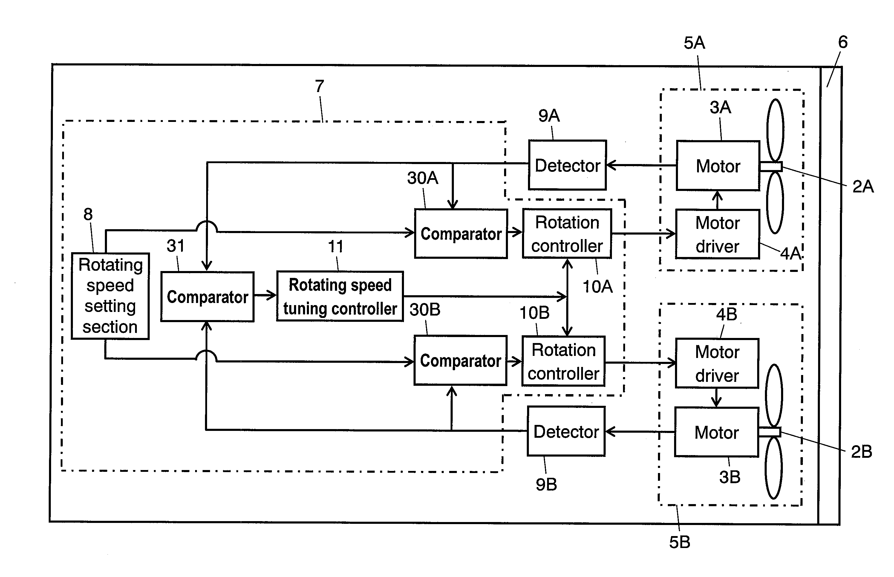
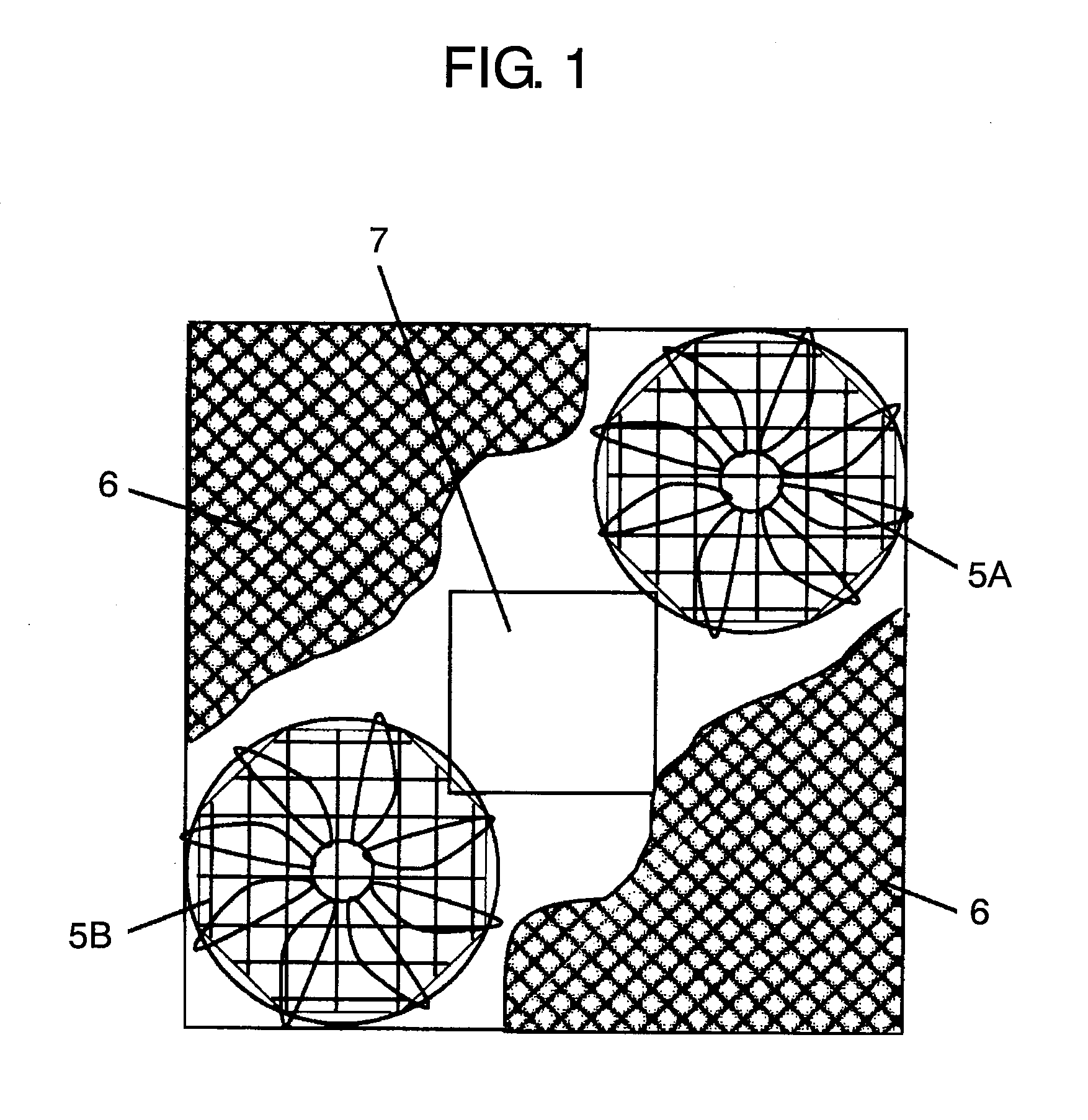
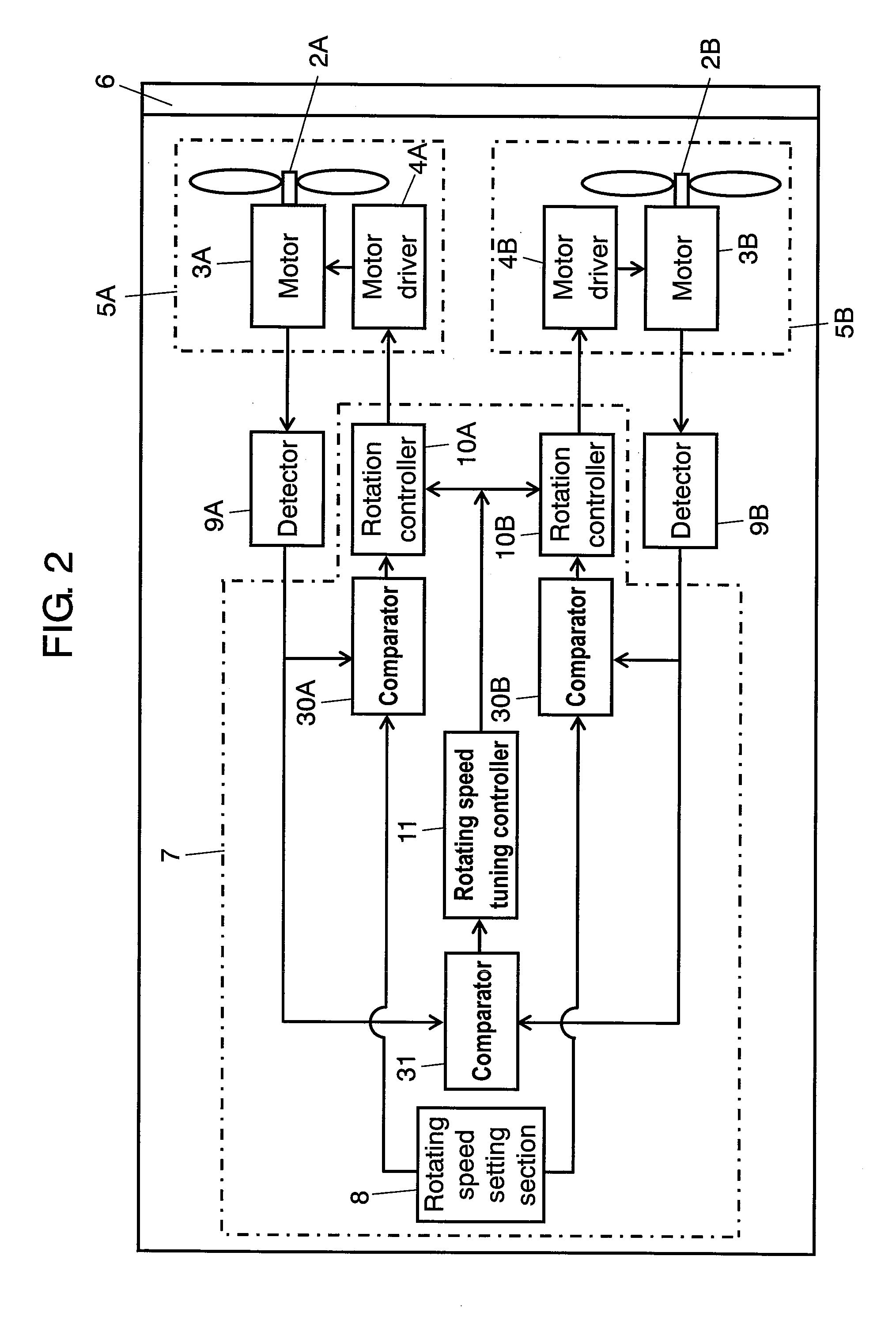
[0015]FIG. 1 illustrates a schematic structure of a fan filter unit according to a first exemplary embodiment of the present invention. FIG. 1 is a front view in which the filter is partially cut out. FIG. 2 is a block circuit diagram thereof. This fan filter unit has first fan motor 5A, second fan motor 5B, and filter 6. Fan motor 5A is composed of first fan 2A, first motor 3A, and first motor driver 4A. Fan motor 5B is composed of second fan 2B, second motor 3B, and second motor driver 4B. Filter 6 cleans air blown by fans 2A and 2B. Filter 6 has glass fibers, for example, and captures micron-order fine particles with a high efficiency. More specifically, filter 6 traps fine particles of 0.3 μm with a trapping efficiency of 99.97% or more. Filter 6 is provided at the blowing side or suction side of fans 2A and 2B.

[0016]Fan filter unit has: total controller 7 (hereinafter referred to as controller 7) configure to control fan motors 5A and 5B; first detector 9A configured to detect ...

second exemplary embodiment

[0026]FIG. 3 is a block circuit diagram illustrating a fan filter unit according to a second exemplary embodiment of the present invention. This exemplary embodiment has the same structure as that of the first exemplary embodiment except for that total controller 73 is structured so that stabilizer 16 is provided between comparator 31 and rotation speed tuning controller 11 (hereinafter referred to as controller 11).

[0027]Stabilizer 16 is designed to prevent controller 11 from functioning until a preparatory operation performed for a predetermined time is completed. Stabilizer 16 prevents controller 11 from functioning in a time zone in which detected rotating speeds of fan motors 5A and 5B are unstable e.g., at a time just after the start of the operation of fan motors 5A and 5B or in a case where the rotating speeds change instantaneously. Stabilizer 16 is also composed by a microcomputer, for example.

[0028]Specifically, when a set rotating speed is 2000 r / min. for example, and de...

third exemplary embodiment

[0031]FIG. 4 is a block circuit diagram illustrating a fan filter unit according to a third exemplary embodiment of the present invention. This exemplary embodiment has the same structure as that of the first exemplary embodiment except for that total controller 74 includes retry section 19. Retry section 19 is also composed of a microcomputer, for example.

[0032]Retry section 19 has a retry function to try to provide a control by which the rotation speeds of fans 2A and 2B are adjusted to a rotating speed set by rotating speed setting section 8, when rotating speed tuning controller 11 (hereinafter referred to as controller 11) continuously performs a tuning control of rotating speed for a predetermined time.

[0033]When fan motors 5A and 5B are stopped during an important process in a clean room using the fan filter unit, the process may have a remarkably-deteriorated productivity. If fan motors 5A and 5B are operated with a low rotating speed, an expected air volume provided by a se...


PUM


Abstract

A fan filter unit includes a plurality of fan motors, a plurality of detectors, a total controller, and a filter. Each of the fan motors includes a fan and a motor. The total controller performs a feedback control to the respective fan motors so that the detected rotating speeds are identical with a set rotating speed, based on rotating speeds detected by the detectors. When one detected rotating speed value by any of the detectors is smaller than the other detected rotating speed value by the other detector, the total controller performs a tuning control of rotating speed so that a rotating speed of the other fan motor is adjusted to the slower rotating speed of the fan motor.

Description

[0001]THIS APPLICATION IS A U.S. NATIONAL PHASE APPLICATION OF PCT INTERNATIONAL PATENT APPLICATION NO. PCT / JP2006 / 302799.TECHNICAL FIELD[0002]The present invention relates to a fan filter unit used in a clean room requiring a clean space for manufacturing semiconductors, liquid crystal or plasma display panels for example.BACKGROUND ART[0003]A fan filter unit is required to have a thin thickness, an opening having a wide area for blowing clean air, and a capability to supply uniform and sufficient air volume. To realize these demands, a plurality of fan motors have been used. The use of a plurality of fan motors, however, may cause a whining sound.[0004]A technique for suppressing the whining sound is disclosed by Japanese Patent Unexamined Publication No. 2004-205095 for example. This technique controls the rotation numbers per a unit time (hereinafter referred to as rotating speed) of a plurality of fan motors, accurately.[0005]In a conventional control for suppressing the whinin...

Claims


Application Information

Patent Timeline
Patent Type & Authority Applications(United States)
IPC IPC(8): F04D27/00
CPCF04D25/166F04D27/004Y02B30/746F24F11/0079F24F2003/1614F24F11/0001F24F11/77Y02B30/70F24F8/108Y02A50/20
Inventor MATSUI, MASAFUMI
Owner PANASONIC CORP
Why Eureka
Try Eureka