Device For Determining A Driving State and Method For The Driving-State-Dependent Operation Of A Combined Vehicle Brake System

a technology of driving state and combined vehicle, which is applied in the direction of braking system, process and machine control, instruments, etc., can solve the problems of vehicle with overbraked rear axle and tendency to experience movement dynamics instability, and achieve the effect of improving energy recovery potential and ensuring vehicle stability

Active Publication Date: 2010-02-04
CONTINENTAL TEVES AG & CO OHG
View PDF16 Cites 17 Cited by
  • Summary
  • Abstract
  • Description
  • Claims
  • Application Information

AI Technical Summary

Benefits of technology

[0011]An object of the present invention is therefore to present a device and a method which detects the driving state of the motor vehicle and adapts it to the distribution of the braking force in such a way that it is possible to improve the energy recovery potential while at the same time ensuring the stability of the vehicle.

Problems solved by technology

In addition, from the theory of movement dynamics it is known that a vehicle with an overbraked rear axle has a tendency to experience movement dynamics instability.

Method used


Image

  • Device For Determining A Driving State and Method For The Driving-State-Dependent Operation Of A Combined Vehicle Brake System
  • Device For Determining A Driving State and Method For The Driving-State-Dependent Operation Of A Combined Vehicle Brake System
  • Device For Determining A Driving State and Method For The Driving-State-Dependent Operation Of A Combined Vehicle Brake System

Examples


Embodiment Construction

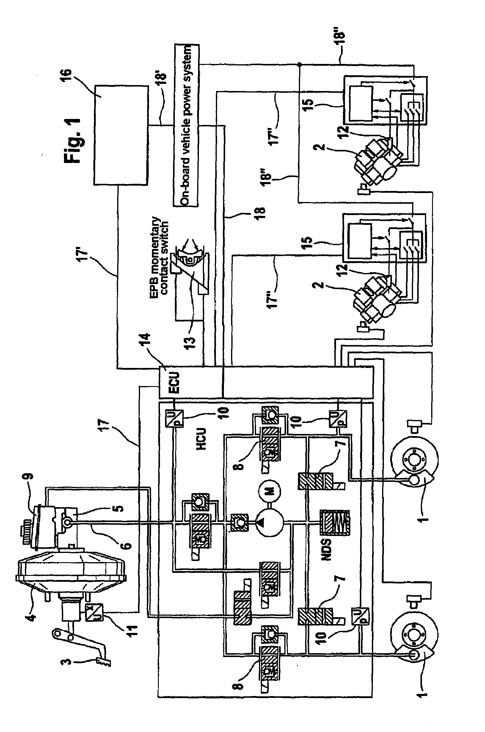
[0022]A circuit diagram of the vehicle brake system on which the method according to aspects of the invention can be carried out is illustrated in FIG. 1. The vehicle brake system has, on the one hand, hydraulically activated wheel brakes 1 and, on the other hand, electromechanically activated wheel brakes 2. The hydraulically activated wheel brakes 1 are arranged on a first axle of the motor vehicle, the front axle, and they have hydraulic pressure medium applied to them using a pedal-activated vacuum brake booster 4 with master brake cylinder 5 connected downstream. For this purpose, the hydraulically activated wheel brakes 1 are connected to the master brake cylinder 5 via a hydraulic line 6 with the intermediate connection of inlet valves 8. When pressure is reduced, the applied pressure medium is let out into an unpressurized pressure medium reservoir vessel 9 via outlet valves 7. In order to detect the applied hydraulic pressure and to carry out regulating processes such as an...


PUM


Abstract

A device for determining a driving state of a two-axle motor vehicle, which driving state is formed from the driving situation of the motor vehicle and the state of the underlying surface, wherein output signals from vehicle on-board sensors are evaluated in order to determine the driving situation and wherein a routine for determining and / or estimating the friction value of the underlying surface is provided in order to determine the state of the underlying surface. Also disclosed is a method for operating a combined vehicle brake system, in particular for motor vehicles, having hydraulically actuable wheel brakes at a front axle and having electromechanically actuable wheel brakes at a rear axle, wherein the vehicle wheels assigned to the rear axle can be driven at least at times by an electric motor which can be operated as a generator for the recuperation of braking energy

Description

CROSS REFERENCE TO RELATED APPLICATIONS[0001]This application is the U.S. national phase application of PCT International Application No. PCT / EP2007 / 062963, filed Nov. 28, 2007, which claims priority to German Patent Application No. DE102006056594.0, filed Nov. 29, 2006 and German Patent Application No. DE102007057605.8, filed Nov. 28, 2007, the contents of such applications being incorporated by reference herein.BACKGROUND OF THE INVENTION[0002]1. Field of the Invention[0003]The invention relates to a device for detecting a driving state of a two-axle motor vehicle.[0004]2. Description of the Related Art[0005]The invention relates to a device for detecting a driving state of a two-axle motor vehicle, which driving state is formed from the driving situation of the motor vehicle and the state of the underlying surface, wherein output signals from vehicle on-board sensors are evaluated in order to determine the driving situation, and wherein a routine for detecting and / or estimating t...

Claims


Application Information

Patent Timeline
Patent Type & Authority Applications(United States)
IPC IPC(8): B60T8/1766
CPCB60T8/1766B60T2270/608B60T8/267
Inventor ROLL, GEORGLEIDECK, JOCHENCISARZ, PETERJAEGER, JENSLINHOFF, PAUL
Owner CONTINENTAL TEVES AG & CO OHG
Why Eureka
Try Eureka