Light emitting device for ac operation

a light emitting device and ac technology, applied in the direction of electroluminescent light sources, electric lighting sources, semiconductor lamp usage, etc., can solve the problems of degrading the light emitting efficiency of the light emitting cells, the led does not continuously emit light, and the heat generation is considerable, so as to prevent excessive reverse voltage, facilitate dissipation, and simplify the process of patterning light emitting cells on the substra

Inactive Publication Date: 2010-02-11
SEOUL VIOSYS CO LTD
View PDF4 Cites 16 Cited by
  • Summary
  • Abstract
  • Description
  • Claims
  • Application Information

AI Technical Summary

Benefits of technology

[0019]According to embodiments of the present invention, since there is provided an AC light emitting device in which a plurality of light emitting cells are flip-bonded to a submount substrate, heat generated from the plurality of light emitting cells connected in series can be easily dissipated through the submount substrate. Further, since bonding patterns and node connecting patterns are formed on the submount substrate, it is possible to prevent excessive reverse voltage from being applied to the light emitting cells. In addition, since it is not required that the light emitting cells share negative electrodes, the processes of patterning light emitting cells on a substrate can be simplified.

Problems solved by technology

As a result, there is a problem in that the LED does not continuously emit light, and is easily broken by a reverse current.
However, in the single chip AC light emitting device, since a plurality of light emitting cells connected in series to one another simultaneously operate, a considerable amount of heat is generated, and such generation of heat causes the light emitting efficiency of the light emitting cells to be degraded.

Method used


Image

  • Light emitting device for ac operation
  • Light emitting device for ac operation
  • Light emitting device for ac operation

Examples


Embodiment Construction

[0026]Hereinafter, preferred embodiments of the present invention will be described in detail with reference to the accompanying drawings. The following embodiments are provided only for illustrative purposes so that those skilled in the art can fully understand the spirit of the present invention. Therefore, the present invention is not limited to the following embodiments but may be implemented in other forms. In the drawings, the widths, lengths, thicknesses and the like of elements may be exaggerated for convenience of illustration. Like reference numerals indicate like elements throughout the specification and drawings.

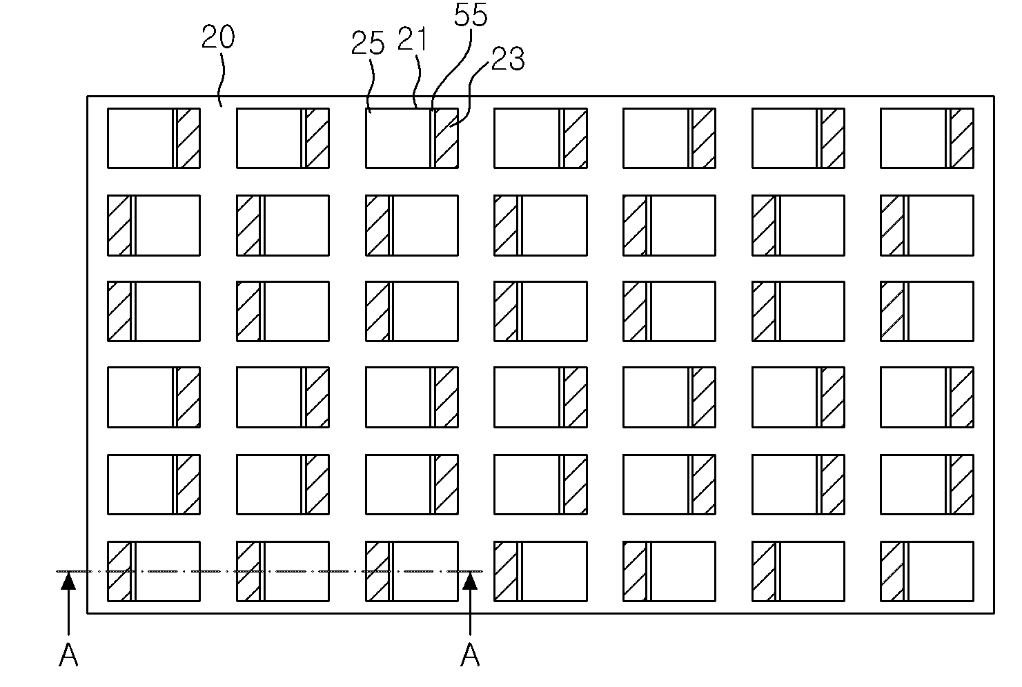
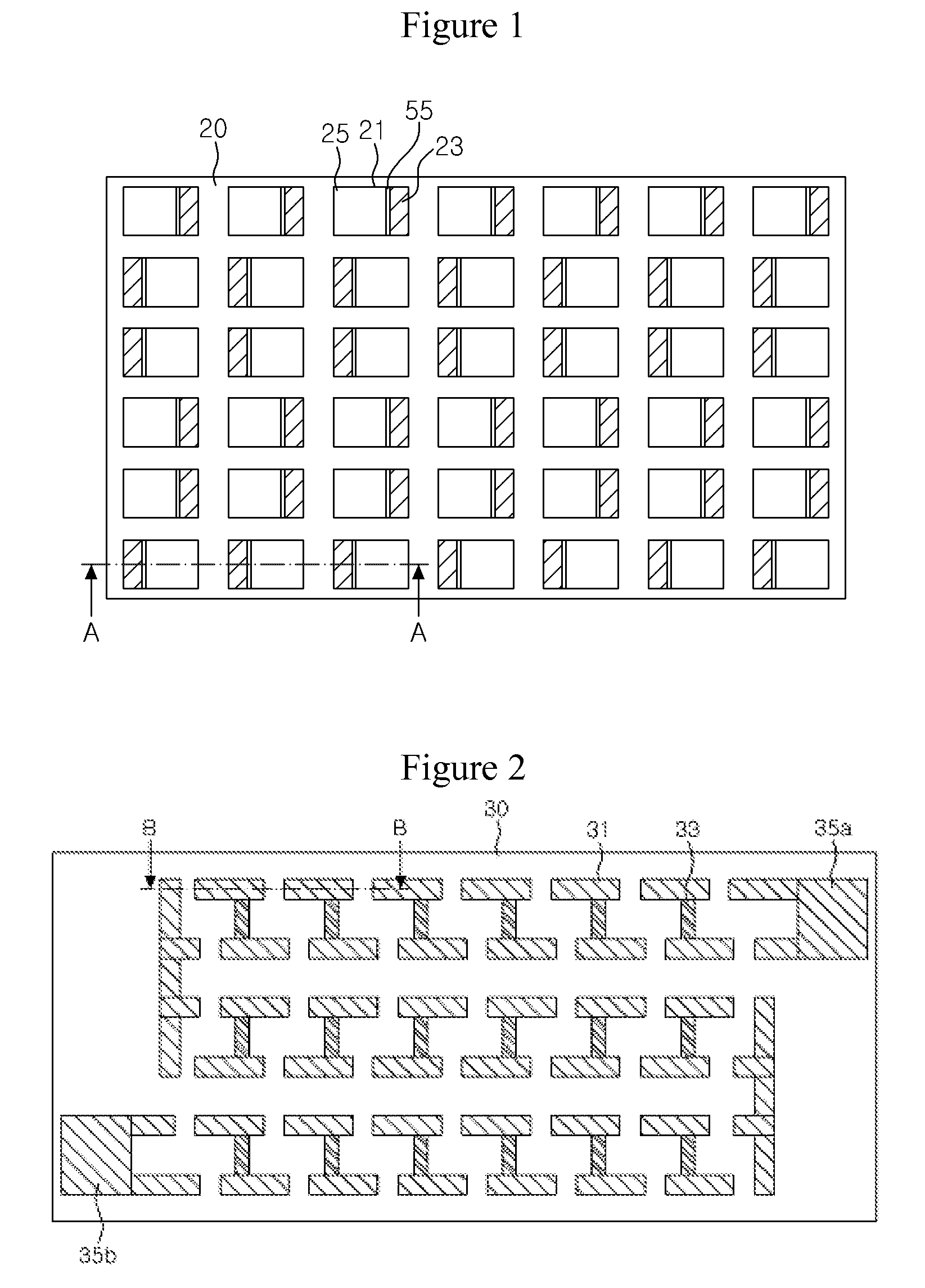
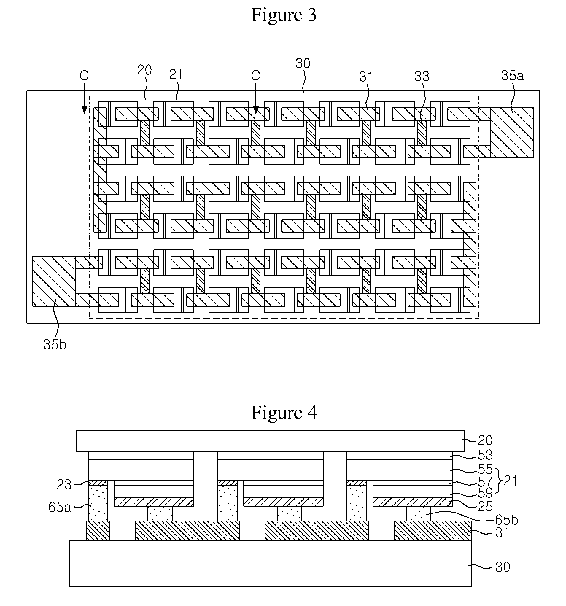
[0027]FIG. 1 is a plan view illustrating an LED having a plurality of light emitting cells according to an embodiment of the present invention, FIG. 2 is a plan view illustrating a submount onto which the LED is flip-bonded according to the embodiment of the present invention, and FIG. 3 is a schematic plan view illustrating an AC light emitting device in which t...


PUM


Abstract

An AC light emitting device, in which a plurality of light emitting cells formed on a substrate are flip-bonded to a submount to be driven under an AC power source is disclosed. The light emitting device comprises a first serial array of light emitting cells, and a second serial array of light emitting cells, wherein the second serial array is connected in reverse parallel to the first serial array. Meanwhile, bonding patterns are formed on a submount substrate, and the light emitting cells of the first and second serial arrays are flip-bonded to the bonding patterns. Further, node connecting patterns are formed on the submount substrate, and connect the bonding patterns such that nodes corresponding to each other provided in the first and second serial arrays are electrically connected to each other. Accordingly, it is possible to provide an AC light emitting device which can prevent overvoltage from being applied to light emitting cells in the array to which reverse voltage is applied by bonding patterns and node connecting patterns formed on a submount substrate, thereby protecting the light emitting cells.

Description

CROSS-REFERENCE TO RELATED APPLICATIONS[0001]This application is the National Stage of International Application No. PCT / KR2007 / 004269, filed Sep. 5, 2007, and claims priority from and the benefit of Korean Patent Application No. 10-2006-0114976, filed on Nov. 21, 2006, which are both hereby incorporated by reference for all purposes as if fully set forth herein.BACKGROUND OF THE INVENTION[0002]1. Field of the Invention[0003]The present invention relates to a light emitting device, and more particularly, to an AC light emitting device, wherein a plurality of light emitting cells formed on a substrate are flip-bonded to a submount to be driven under an AC power source.[0004]2. Discussion of the Background[0005]With the development of GaN based light emitting diodes (LEDs), the GaN based LEDs have considerably changed LED technologies. Currently, the GaN based LEDs are used for various applications such as a full-color LED display, an LED traffic light, a white LED, and the like. Rece...

Claims


Application Information

Patent Timeline
Patent Type & Authority Applications(United States)
IPC IPC(8): H01L33/00H01L33/62
CPCH01L25/0753H01L33/62H05B33/0803H05B33/0821H05B33/089H01L2924/0002Y02B20/341H01L2924/00Y02B20/30H05B45/30H05B45/42H05B45/56
Inventor LEE, KEON YOUNGKAL, DAE SUNG
Owner SEOUL VIOSYS CO LTD
Why Eureka
Try Eureka