Fixing device and image forming apparatus employing the fixing device

a fixing device and fixing device technology, applied in the direction of electrographic process apparatus, ohmic resistance heating, instruments, etc., can solve the problems of lengthening warm-up time and lengthening warm-up time, and achieve the effect of effective heating the temperatur

Active Publication Date: 2010-02-11
RICOH KK
View PDF14 Cites 43 Cited by
  • Summary
  • Abstract
  • Description
  • Claims
  • Application Information

AI Technical Summary

Benefits of technology

[0013]The present disclosure provides a fixing device capable of effectively raising the temp

Problems solved by technology

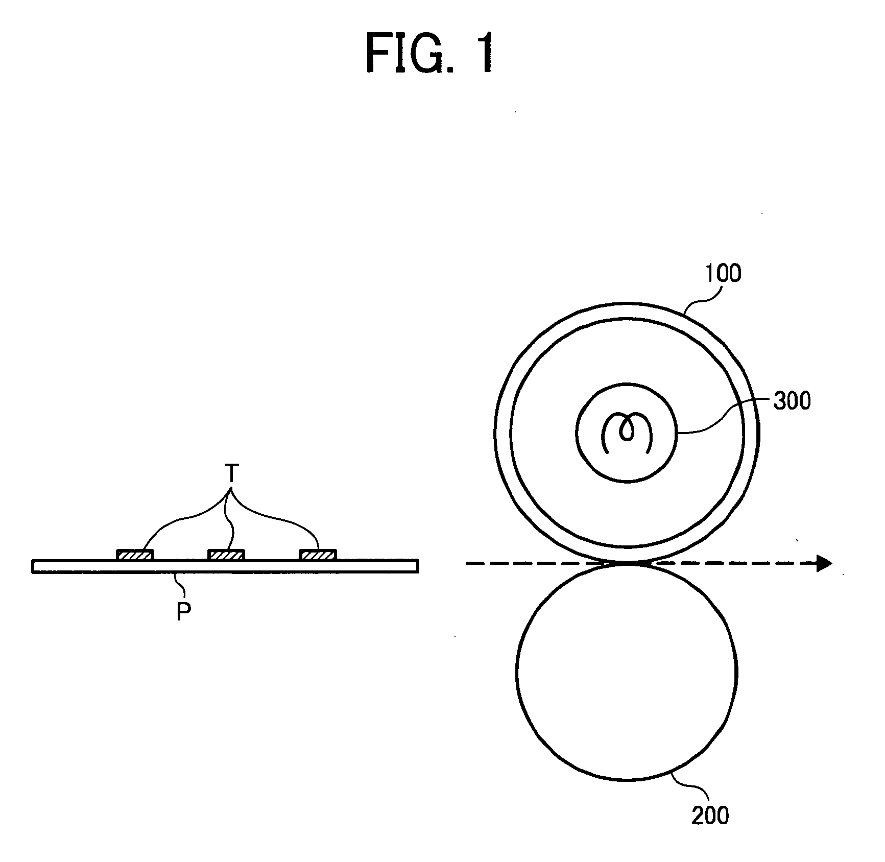
However, in the warm-up operation, heat is radiated from the pressure roller 200, thus lengthening warm-up time.
However, in such cases, since the fixing roller and the pressure roller contact each

Method used


Image

  • Fixing device and image forming apparatus employing the fixing device
  • Fixing device and image forming apparatus employing the fixing device
  • Fixing device and image forming apparatus employing the fixing device

Examples


Embodiment Construction

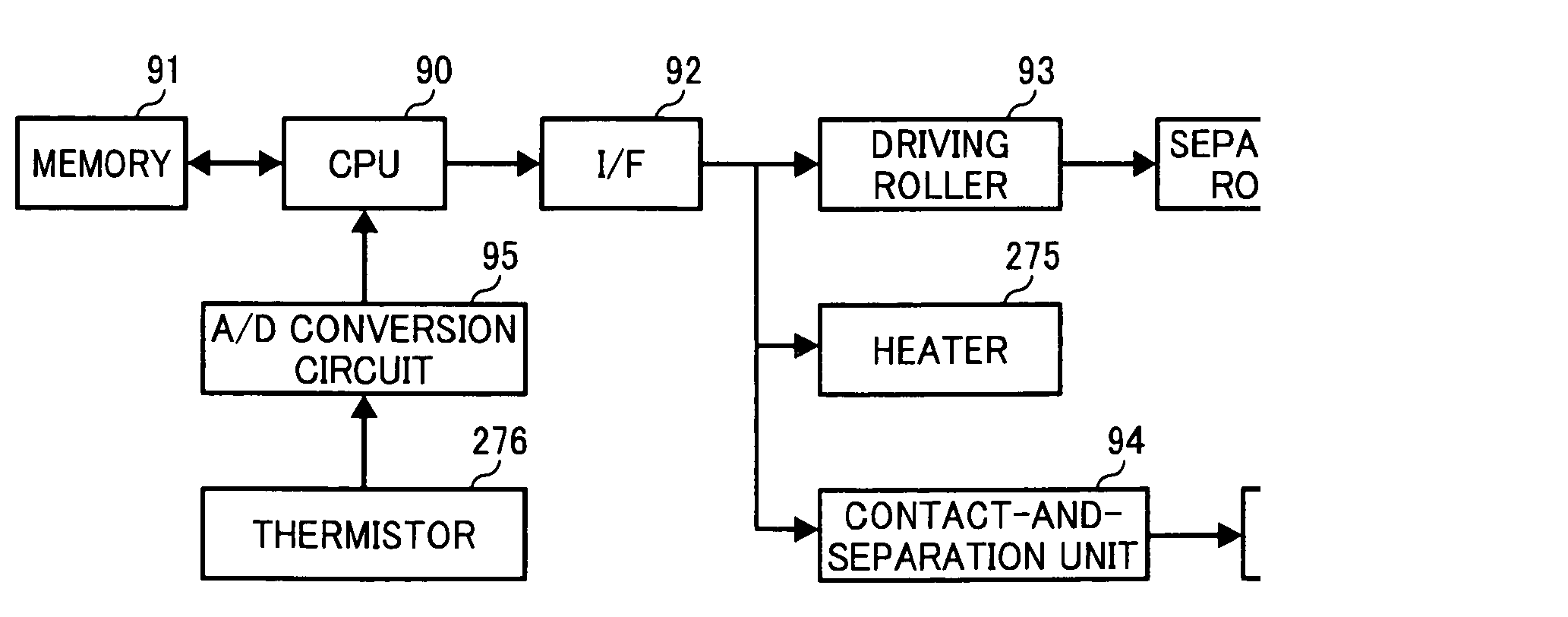
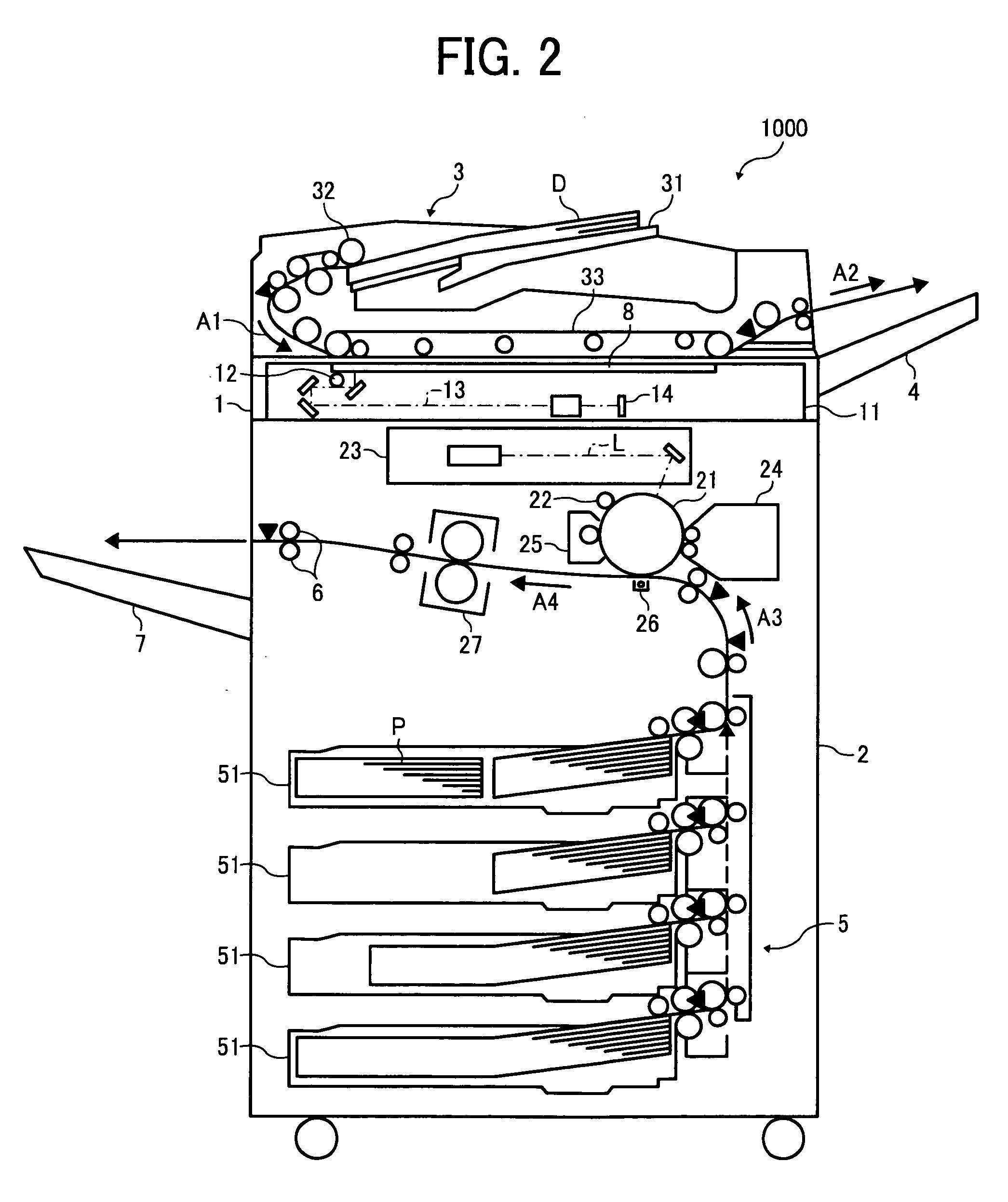
[0028]In describing embodiments illustrated in the drawings, specific terminology is employed for the sake of clarity. However, the disclosure of this patent specification is not intended to be limited to the specific terminology so selected and it is to be understood that each specific element includes all technical equivalents that operate in a similar manner and achieve similar results.

[0029]Although the illustrative embodiments are described with technical limitations with reference to the attached drawings, such description is not intended to limit the scope of the present invention and all of the components or elements described in the illustrative embodiments of this disclosure are not necessarily indispensable to the present invention.

[0030]Below, illustrative embodiments according to the present invention are described with reference to attached drawings.

[0031]FIG. 2 is a schematic view illustrating a configuration of an electrophotographic image forming apparatus 1000 acco...


PUM


Abstract

A fixing device includes a rotary fixing member, a counter member to contact the rotary fixing member, a first heater to heat the rotary fixing member, a driving unit to rotate the rotary fixing member, a temperature detector to detect a temperature of the rotary fixing member, and a contact-and-separation unit to switch between contact and separation states of the rotary fixing member relative to the counter member. In a temperature-raising operation, the driving unit causes the rotary fixing member to rotate when the temperature detector detects that the temperature of the rotary fixing member has reached a first setting temperature. The contact-and-separation unit causes the rotary fixing member in rotation and the counter member to contact each other when the temperature detector detects that the temperature of the rotary fixing member has reached a second setting temperature that is higher than the first setting temperature.

Description

CROSS-REFERENCE TO RELATED APPLICATIONS[0001]The present patent application claims priority pursuant to 35 U.S.C. §119 from Japanese Patent Application Nos. 2008-205737, filed on Aug. 8, 2008, and 2009-085467, filed on Mar. 31, 2009 in the Japan Patent Office, each of which is hereby incorporated-herein by reference in its entirety.BACKGROUND OF THE INVENTION[0002]1. Field of the Invention[0003]Illustrative embodiments of the present invention relate to a fixing device and an image forming apparatus, such as a copier and a laser printer, employing the fixing device.[0004]2. Description of the Background[0005]An image forming apparatus is used as a printer, a facsimile machine, a copier, a plotter, or a multi-functional peripheral having several of the foregoing capabilities. One conventional image forming apparatus performs image formation by an electrographic method. Such an electrophotographic image forming apparatus includes a fixing device that fixes a toner image on a recording...

Claims


Application Information

Patent Timeline
IPC IPC(8): G03G15/20
CPCG03G15/2039G03G15/2032
Inventor NAITOH, YUTAKAOGISO, TOSHIOIKEDA, TAMOTSU
Owner RICOH KK
Why Eureka
Try Eureka