Interlocking connector system

a connector system and interlocking technology, applied in the direction of fastening means, rod connections, couplings, etc., can solve the problems of difficult and time-consuming use of fastening techniques, damage to existing bracket designs, and damage to furniture, etc., to achieve tight and strong connection

Active Publication Date: 2010-02-11
HOWLETT ENTERPRISES
View PDF10 Cites 12 Cited by
  • Summary
  • Abstract
  • Description
  • Claims
  • Application Information

AI Technical Summary

Benefits of technology

[0011]A further object of the present invention is to provide an interlocking connector system that has the ability to tighten joints without mechanical clamps, that can be concealed as a straight bracket, that allows for easy disassembly and reassembly, that has sufficient structural integrity to allow relocation of case goods without disassembly, that does not require power tools for assembly after the bracket members are installed, that allows case goods to be shipped unassembled to reduce the cost of freight, and that can be easily assembled to reduce the cost of labor.

Problems solved by technology

However, these fastening techniques have often been difficult and time consuming to use, particularly by unskilled consumers or furniture retailers who purchase items that must be assembled after shipment.
The use of screws by furniture installers often results in “screw run through,” which can severely damage the furniture.
While some of the problems of using traditional fasteners have been addressed in the prior art by using various brackets, the existing bracket designs have also had problems.
For example, conventional brackets are difficult to conceal and / or lack sufficient structural integrity after assembly to securely tighten joints or to allow the attached items to be moved without damaging the connection.
However, this system cannot be easily concealed in an item of furniture and would be difficult for some users to obtain perfect alignment between the objects being connected.
However, these mating parts are incorporated into the components being mounted together, and are not provided as a separate mounting system that can be attached by screws to furniture parts, etc.

Method used


Image

  • Interlocking connector system
  • Interlocking connector system
  • Interlocking connector system

Examples


first embodiment

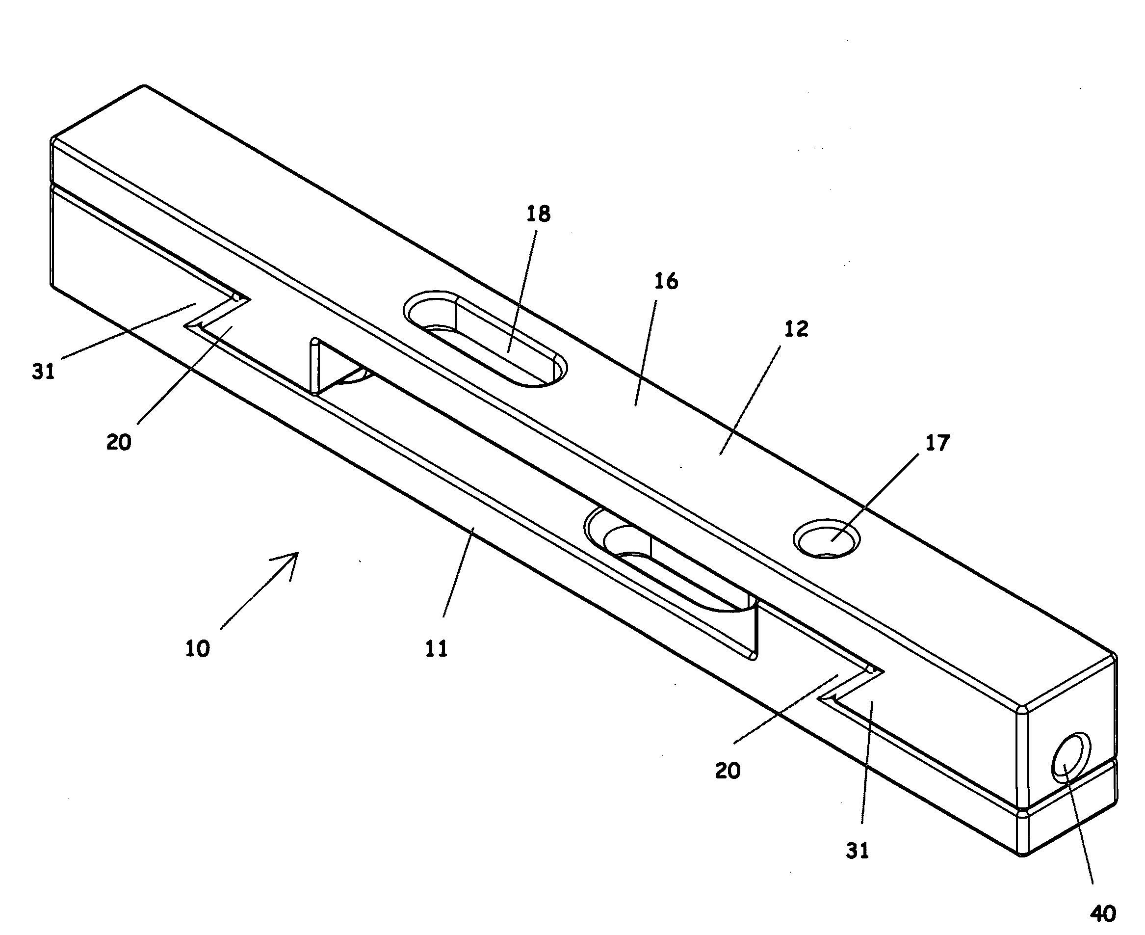
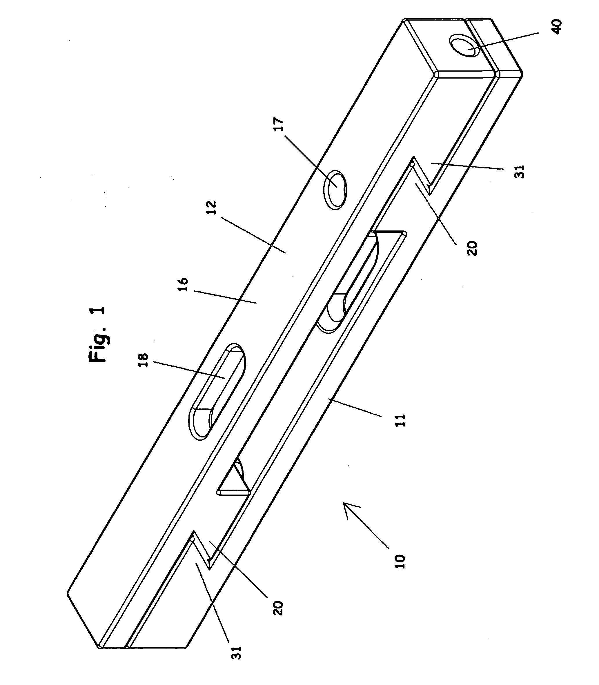
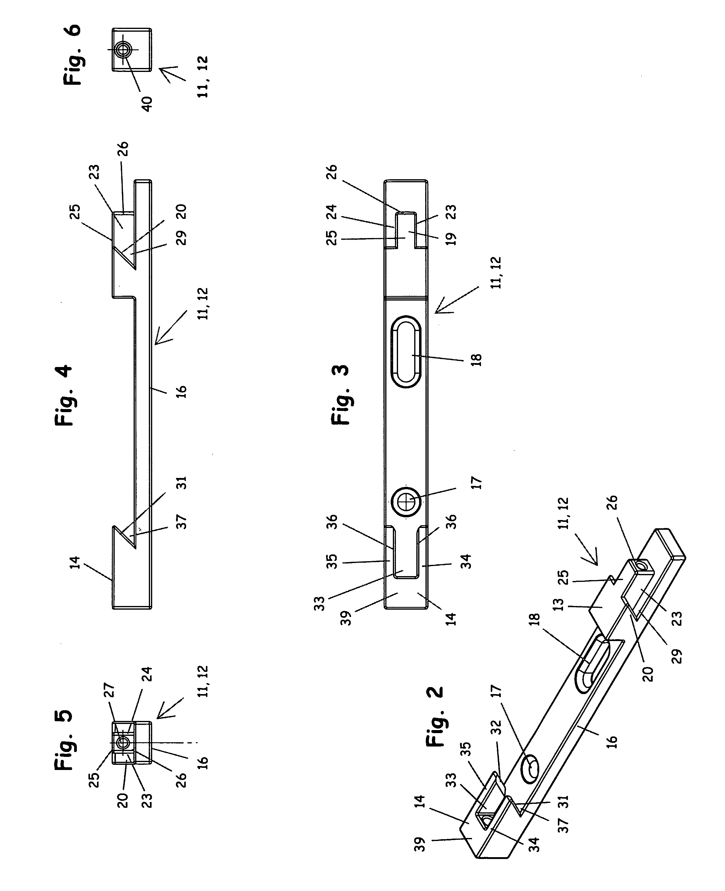
[0069]An interlocking connector system 10 is shown in FIGS. 1 to 6. The connector system 10 of this embodiment includes a first connector member 11 and a second connector member 12 that can each be mounted to separate objects and then interlocked together to attach the two objects together. The first and second connector members 11, 12 are identical and interchangeable with each other.

[0070]The connector members 11, 12 each have an alignment structure 13 at one end, and a receiver structure 14 at the other end. An elongate body 15 extends between the alignment structure 13 and the receiver structure 14. The elongate body 15 has a substantially flat mounting surface 16 on a backside for engaging an object on which the connector member 11, 12 is mounted. At least one, and preferably a plurality of, mounting openings 17, 18 are provided in the elongate body for receiving threaded fasteners or the like (not shown) to secure the connector member 11, 12 to an object. At least one of the ...

second embodiment

[0079]A connector system 10′ is shown in FIGS. 7 to 15. The connector system 10′ is similar to the connector system 10 shown in FIGS. 1 to 6, and therefore the same reference numerals have been used to designate the elements that are substantially the same in each embodiment. In addition to the common elements described above, the connector system 10′ also includes egress openings 30 formed in the body 15 adjacent each side of the projection 19 to allow dust and other particles to pass through without interfering with the connection. The connector system 10 also has one or more bores 41 formed in the sidewalls 34, 35 of the receiver structure 14 for receiving one or more threaded set screws 42. The set screws 42 can be used in the bores 41 to anchor the assembled connector members 11, 12 together.

[0080]The interlocking connector systems 10 and 10′ described above can be used to connect various objects together. For example, two panels of a desk or other item of furniture can be sec...


PUM


Abstract

An interlocking connector system includes two connector members that can each be mounted to separate objects and then interlocked together to attach the two objects together. In one embodiment, the two connector members are identical and interchangeable with each other. In other embodiments, the two connector members are arranged to attach together objects having perpendicular mounting surfaces or coplanar mounting surfaces. The connector members include an alignment structure having a projection positioned between a first pair of inclined surfaces, and a receiver structure positioned between a second pair of inclined surfaces. The connector members are interlocked together by mating the alignment structure of one connector member with the receiver structure of the other connector member. The relative movement between the connector members causes the inclined surfaces of one connector member to wedge against the inclined surfaces of the other connector member to form a tight and strong connection.

Description

RELATED APPLICATIONS[0001]This application claims priority of U.S. Provisional Application No. 61 / 086,390 filed on Aug. 5, 2008. The content of this prior application is incorporated herein by reference.BACKGROUND OF THE INVENTION[0002]1. Field of the Invention[0003]The present invention relates generally to connectors to attaching objects together, and in particular to an interlocking connector system that can be mounted to separate objects and then interlocked together to attach the objects together.[0004]2. Description of the Related Art[0005]Many techniques exist in the prior art for attaching objects together. For example, screws, nails, dowels, and bolts have been used to attach objects together, such as furniture components, shelves, book cases, etc. However, these fastening techniques have often been difficult and time consuming to use, particularly by unskilled consumers or furniture retailers who purchase items that must be assembled after shipment. The use of screws by fu...

Claims


Application Information

Patent Timeline
Patent Type & Authority Applications(United States)
IPC IPC(8): F16B9/02
CPCF16B5/0052Y10T403/63Y10T403/7069
Inventor HOWLETT, HAROLD DEAN
Owner HOWLETT ENTERPRISES
Why Eureka
Try Eureka