Electric power equipment metal mold casting combined mold

A technology for metal mold casting and electrical equipment, which is applied in manufacturing tools, casting molding equipment, metal processing equipment, etc., can solve problems such as the shape or fineness of the mold core, and achieve difficult transformation, save expensive materials, and improve utilization. Effect

Pending Publication Date: 2022-03-25
张若玮
View PDF0 Cites 0 Cited by
  • Summary
  • Abstract
  • Description
  • Claims
  • Application Information

AI Technical Summary

Problems solved by technology

[0006] Aiming at the above problems, the present invention provides a combined mold for metal mold casting for electrical equipment. The mold core composed of the combined mold core frame and various types of mold plates is movably connected, and can achieve complex shapes or precise structures after trimming. Metal mold casting mold requirements; basically solve the problem of the existing combined mold on the shape or fineness of the mold core; and expand the adjustable range of the metal casting combined mold under the condition of using the original components; Disassemble and reorganize the scrapped combined mold to improve its utilization rate

Method used


Image

  • Electric power equipment metal mold casting combined mold
  • Electric power equipment metal mold casting combined mold
  • Electric power equipment metal mold casting combined mold

Examples


Embodiment Construction

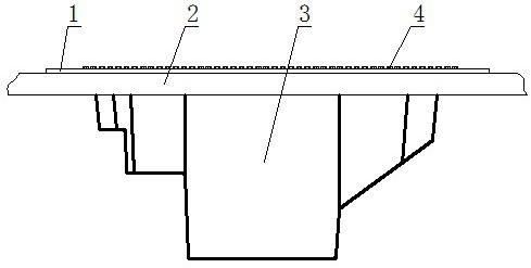
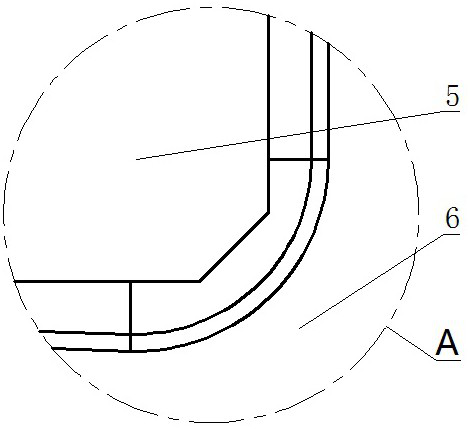
[0026] As shown in the figure, its preferred embodiment is: the movable interconnection mechanism 7 is all established around the mold column assembly 12, and the mold column assembly 12 can be directly and flexibly connected around, and the top of the mold column assembly 12 is provided with a nut column 13 , the nut column 13 is fixed on the top of the mold column assembly 12 .

[0027] The bolt 4 is screwed into the screw hole 14 of the positioning plate 1, and then screwed into the nut column 13 of the mold column assembly 12 after passing through the screw hole 14. Among them, the independent positioning of the bolt 4 and the height positioning of the mold column assembly 12 are realized, and the height of the mold column assembly 12 can be adjusted with high precision only by rotating the bolt 4 .

[0028] The mold column assembly 12 is composed of mold column units of various lengths to form mold column assemblies 12 of various lengths, which are arranged on the corresp...


PUM


Abstract

The electric power equipment metal mold casting combined mold is characterized in that mold column assemblies are provided with movable interconnection mechanisms, the mold column assemblies can be directly and movably connected, and nut columns are arranged at the top ends of the mold column assemblies; the bolt is screwed into the screw hole of the positioning plate, penetrates out of the screw hole and then is screwed into the nut column of the die column assembly, and when the bolt is screwed to the bottom, the thin shaft end at the root of the bolt is embedded into the screw hole, so that the bolt is positioned and the telescopic length of the die column assembly is positioned; the combined mold core frameworks in various shapes can be formed through various connection and combination modes of the mold column assemblies, and the mold frame is fixed after being nested in the combined mold core frameworks; the adjustable interconnection mechanism is nested in the movable interconnection mechanism at the outer end of the combined mold core framework, the mold transverse plate, the mold longitudinal plate and the mold special-shaped plate are movably connected with the adjustable interconnection mechanism, and the lower mold plate and the upper mold plate are connected with through holes of the mold column assembly. The fine difference between the combined metal mold casting mold and an ideal casting model can be compensated by nesting the lining plate of the mold plate, so that the advantage that the lining plate is easy to process can be fully utilized, and a complete combined mold core with a complex shape or a precise structure can be formed after finishing.

Description

technical field [0001] The invention relates to a metal mold for casting. Background technique [0002] Metal mold casting, also known as hard mold casting, is a widely used casting form. Non-ferrous alloy castings such as bronze, brass, and aluminum can be obtained by metal mold casting. Metal mold casting is a casting method in which liquid metal is first poured into a metal mold, then kept for an appropriate time, and finally the mold is opened to take out the casting after the metal solidifies to obtain a casting. [0003] Because the castings produced by metal mold casting, first, their mechanical properties are higher than those of sand castings. For the same alloy, the tensile strength can be increased by 25% on average, the yield strength can be increased by about 20% on average, and its corrosion resistance and hardness are also significantly improved. Second, the precision and surface finish of castings are higher than those of sand castings, and the quality and d...

Claims


Application Information

Patent Timeline
IPC IPC(8): B22C9/06B22C9/10
CPCB22C9/06B22C9/064B22C9/108
Inventor 张若玮
Owner 张若玮
Why Eureka
Try Eureka