Tube-and-tube annular channel double-sided heat exchange large-flux microchannel fixed-bed reactor

A technology of fixed bed reactor and annular channel, which is applied in chemical/physical/physicochemical fixed reactors, etc., can solve the problems of large fluid resistance, overheating reaction temperature, loss of control, etc., and achieve convenient replacement and regeneration, and production Simplicity and safety-enhancing effect

Inactive Publication Date: 2015-10-28
石祖嘉
View PDF4 Cites 0 Cited by
  • Summary
  • Abstract
  • Description
  • Claims
  • Application Information

AI Technical Summary

Problems solved by technology

Disadvantages are: (1) poor heat transfer, when the heat of reaction is large, even the shell-and-tube reactor may have a runaway temperature (reaction temperature is out of control, rises sharply, exceeding the allowable range); (2) catalyst regeneration and It is inconvenient to replace; (3) The particles of the catalyst cannot be too fine, otherwise the fluid resistance will be large and the normal operation will be destroyed, so the active inner surface of the catalyst cannot be fully utilized
At present, for this type of reaction, the simplest microreactor is to make a microchannel first, and then use various methods such as impregnation and sintering to fix the catalyst on the wall of the microchannel. The manufacturing process is cumbersome and complicated, and catalyst replacement and regeneration are difficult. ; The Massachusetts Institute of Technology has developed a micro-packed bed reactor, in which microchannels are filled with catalyst solid particles, and its structure is similar to that of a fixed-bed reactor. This reactor solves the problems of heat transfer and mass transfer in traditional reactors. It also has the advantages of high selectivity and low catalyst loss in fixed bed reactors, but the problems of catalyst replacement, regeneration and fluid pressure drop still exist
In addition, like other types of microreactors, there is a fatal shortcoming, that is, it is impossible to achieve large throughput.

Method used


Image

  • Tube-and-tube annular channel double-sided heat exchange large-flux microchannel fixed-bed reactor
  • Tube-and-tube annular channel double-sided heat exchange large-flux microchannel fixed-bed reactor
  • Tube-and-tube annular channel double-sided heat exchange large-flux microchannel fixed-bed reactor

Examples


Embodiment Construction

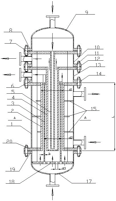
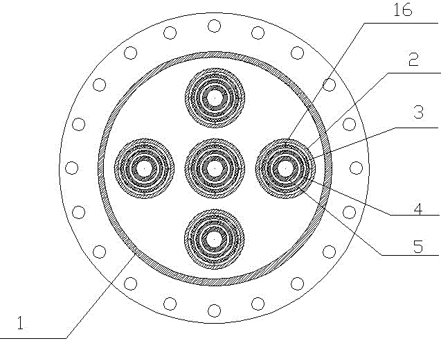
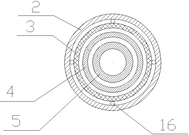
[0033] Such as Figure 1-3 As shown, the tubular annular channel double-sided heat exchange large-flux microchannel fixed-bed reactor includes: cylinder 1, column tube 2, catalyst tube 3, middle sleeve 4, inner sleeve 5, and No. 1 flange 6, No. 3 flange tube plate 7, No. 3 flange 8, No. 1 head 9, No. 2 tube box 10, No. 2 flange 11, No. 2 flange tube plate 12, No. 1 tube box 13, No. 1 Flange tube plate 14, baffle plate 15, fixed-distance round steel 16, No. 2 head 17, support flower plate 18, No. 4 flange 19 and No. 4 flange tube plate 20, one end of the cylinder 1 is welded together No. 14 flange tube plate, the other end of the cylinder body 1 is welded to the No. 4 flange tube plate 20, the cylinder body 1 has a baffle plate 15, and the cylinder body 1 is provided with a heat exchange medium inlet and heat exchange For the medium outlet, the tube 2 is sleeved in the cylinder 1, one end of the tube 1 is welded to the No. 1 flange tube plate 14, the other end of the tube 1 is w...


PUM


Abstract

The invention discloses a tubular type annular channel double-sided heat-exchange large-flux microchannel fixed bed reactor. The reactor is sleeved in a tube (2) through a catalyst pipe (3), a middle sleeve (4) is sleeved in the catalyst pipe (3), a double-annular clearance microchannel is formed between the catalyst pipe (3) and the tube (2) and another double-annular clearance microchannel is formed between the catalyst pipe (3) and the middle sleeve (4), the space of the annular clearances is 0.05-5mm, and 0.2-2mm is the best. The reactor has all the advantages of a microreactor and a filling bed reactor, the defect that pressure drop is generated to damage normal operation when the fluid of a filling bed flows in a bed layer and the difficulty that the flux of the microreactor is universally small can be solved, more than 98% of catalysts can be saved by replacing a hydrogenated reaction kettle with the reactor, the temperature of the bed layers of the reactor is even, and the defect that the fixed bed reactor easily generates temperature runaway can be overcome.

Description

Technical field [0001] The invention relates to a microreactor, in particular to a tube-and-tube annular channel double-sided heat exchange large flux microchannel fixed bed reactor. Background technique [0002] In chemical production, the traditional fixed-bed reactor is also called a packed-bed reactor, which is filled with solid catalysts (granular, mesh, honeycomb, fibrous, etc.) or solid reactants to achieve a multiphase reaction process. Device. The bed is stationary, and the fluid passes through the bed to react. Compared with other traditional reactors, the fixed bed reactor has its own advantages and disadvantages. The advantages are: (1) The backmixing is small, and the fluid can effectively contact the catalyst. When the reaction is accompanied by a series of side reactions, a higher choice can be obtained. (2) The catalyst has low mechanical loss and long service time; (3) Simple structure; (4) Suitable for high temperature and high pressure operation. The disadva...

Claims


Application Information

Patent Timeline
Patent Type & Authority Patents(China)
IPC IPC(8): B01J19/24
Inventor 石祖嘉
Owner 石祖嘉
Why Eureka
Try Eureka