HIFU treatment probe

a technology of hifu treatment and probes, which is applied in the field of high-intensity focused ultrasound (hifu), can solve the problems of difficult sterilization of current hifu treatment probes, and achieve the effects of facilitating device cleaning, reducing obstructions, and reducing the number of hifu treatment probes

Inactive Publication Date: 2010-02-11
US HIFU
View PDF10 Cites 12 Cited by
  • Summary
  • Abstract
  • Description
  • Claims
  • Application Information

AI Technical Summary

Benefits of technology

[0012]This construction essentially eliminates obstructions in the bolus chamber and facilitates the cleaning of the device. The bolus chamber being essentially free of structures that would trap blood and organic contaminants from a patient promotes cleaning and sterilization.
[0013]The cylinder is preferably one of two support cylinders spaced longitudinally from one another along the transducer shaft. The other of the two support cylinders is likewise provided in a distal end surface with a seal about the transducer shaft. The sleeve or shaft housing construction of the present invention permits the removal of the outer and inner sleeves and enables access to the space between the two support cylinders for cleaning purposes.
[0014]Pursuant to another feature of the present invention, the translatory drive assembly includes a rotary output shaft assembly having a single bearing. The bearing is disposed on the frame at a forward or distal end of the rotary output shaft assembly, while the translatory drive assembly includes a motor mounted to

Problems solved by technology

Current HIFU treatment probes are difficult to sterilize particularly in the event that the

Method used


Image

  • HIFU treatment probe
  • HIFU treatment probe
  • HIFU treatment probe

Examples


Embodiment Construction

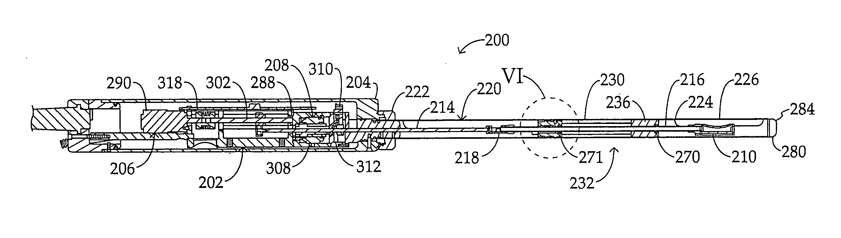
[0036]As depicted in FIG. 5, a high-intensity focused ultrasound device 200 comprises a frame 202, a handle casing or housing 204 surrounding the frame, a translatory drive assembly 206 mounted to the frame and disposed inside the casing, a rotary drive assembly 208 mounted to the frame and disposed inside the casing, and a focused ultrasound transducer 210. Translatory drive assembly 206 and rotary drive assembly 208 are operatively connected to transducer 210 via a mechanical transmission train 212 including an upstream or proximal transducer shaft section 214 and a downstream of distal drive shaft section 216. The transducer drive sections 214 and 216 are linked to one another via a transducer shaft coupling 218. Upstream or proximal transducer drive shaft section 214 is operatively connected at an upstream or input end to translatory drive assembly 206 and rotary drive assembly 208, while downstream or distal transducer shaft section 216 is connected at a forward or distal end t...


PUM


Abstract

A high-intensity focused ultrasound device with a translatory dive assembly and a rotary drive assembly mounted to a single-piece frame and disposed therewith inside a handle casing includes a focused ultrasound transducer driven by the drive assemblies via a pair of transducer shafts surrounded by an inner sleeve and outer sleeve that sandwich a bolus tube, the outer sleeve being slidably removable from atop the inner sleeve.

Description

CROSS-REFERENCE TO RELATED APPLICATION[0001]This application claims the benefit under 35 U.S.C. §119(e) of U.S. Provisional Patent Application No. 61 / 137,962 filed 5 Aug. 2008 and U.S. Provisional Patent Application No. 61 / 188,734 filed 12 Aug. 2008.BACKGROUND OF INVENTION[0002]This invention relates to high-intensity focused ultrasound (HIFU) for use in treating patients' internal tissue structures. More particularly the present invention relates to improvements in HIFU treatment probes.[0003]High-intensity focused ultrasound (HIFU) devices are used in medicine to remove or neutralize malignant or diseased tissue. All high-intensity focused ultrasound (HIFU) devices currently on the market include a therapy transducer, a diagnostic transducer and a computer controlled electrical signal generator with integrated diagnostic systems. In practice, both the diagnostic and therapy transducers are allowed two degrees of freedom. One degree is longitudinal with respect to the axis of the d...

Claims


Application Information

Patent Timeline
IPC IPC(8): A61N7/02
CPCA61B2017/00084A61N7/022A61B2018/00023
Inventor ISOLA, SCOTTMANNA, RONALD R.VOIC, DAN
Owner US HIFU
Why Eureka
Try Eureka