Method for Predicting Flow and Performance Characteristics of a Body Using Critical Point Location

a critical point location and flow prediction technology, applied in the direction of instruments, cad techniques, analogue processes for specific applications, etc., can solve the problems of a fundamental mathematical drawback, the general use of methods that fail to predict the hysteresis of pitching oscillations of airfoils, and the increase of errors in computed performan

Inactive Publication Date: 2010-02-11
TAO OF SYST INTEGRATION
View PDF0 Cites 24 Cited by
  • Summary
  • Abstract
  • Description
  • Claims
  • Application Information

AI Technical Summary

Benefits of technology

[0014]The methods and systems of the invention provide improved predictions for the aerodynamic performance of wing sections, optimization of wind designs based on aerodynamic perf

Problems solved by technology

However, errors in the computed performance are known to increase significantly in the presence of flow separation near stall and post-stall conditions.
Further, the generally used methods fail to predict hysteresis when an airfoil undergoes pitching oscillations.
NACA TR 452 (1933)), when the lift coefficient varied almost linearly with α. This approach gave poor results in the presence of extensive flow separation on the suction side of the airfoil upstream of the trailing edge at high α, near and beyond stall (see de Vargas, L. A. T., de Oliveira, P. H. I., de Freitas Pinto, R. L. U., Bortoulus, M. V., and e Souza, M. da Silva.
The curr

Method used


Image

  • Method for Predicting Flow and Performance Characteristics of a Body Using Critical Point Location
  • Method for Predicting Flow and Performance Characteristics of a Body Using Critical Point Location
  • Method for Predicting Flow and Performance Characteristics of a Body Using Critical Point Location

Examples


Embodiment Construction

[0024]While the invention will be described in connection with the preferred embodiment, it will be understood that it is not intended to limit the invention to those embodiments. On the contrary, it is intended to cover all alternatives, modifications and equivalents that may be included within the spirit and scope of the invention as described.

[0025]An embodiment of the invention provides a method for predicting the performance of a wing section. Another embodiment provides a method for designing a wing section given performance requirements and constraints. Still another embodiment provides a method for measuring aerodynamic performance using flow bifurcation point measurements in conjunction with other sensor measurements.

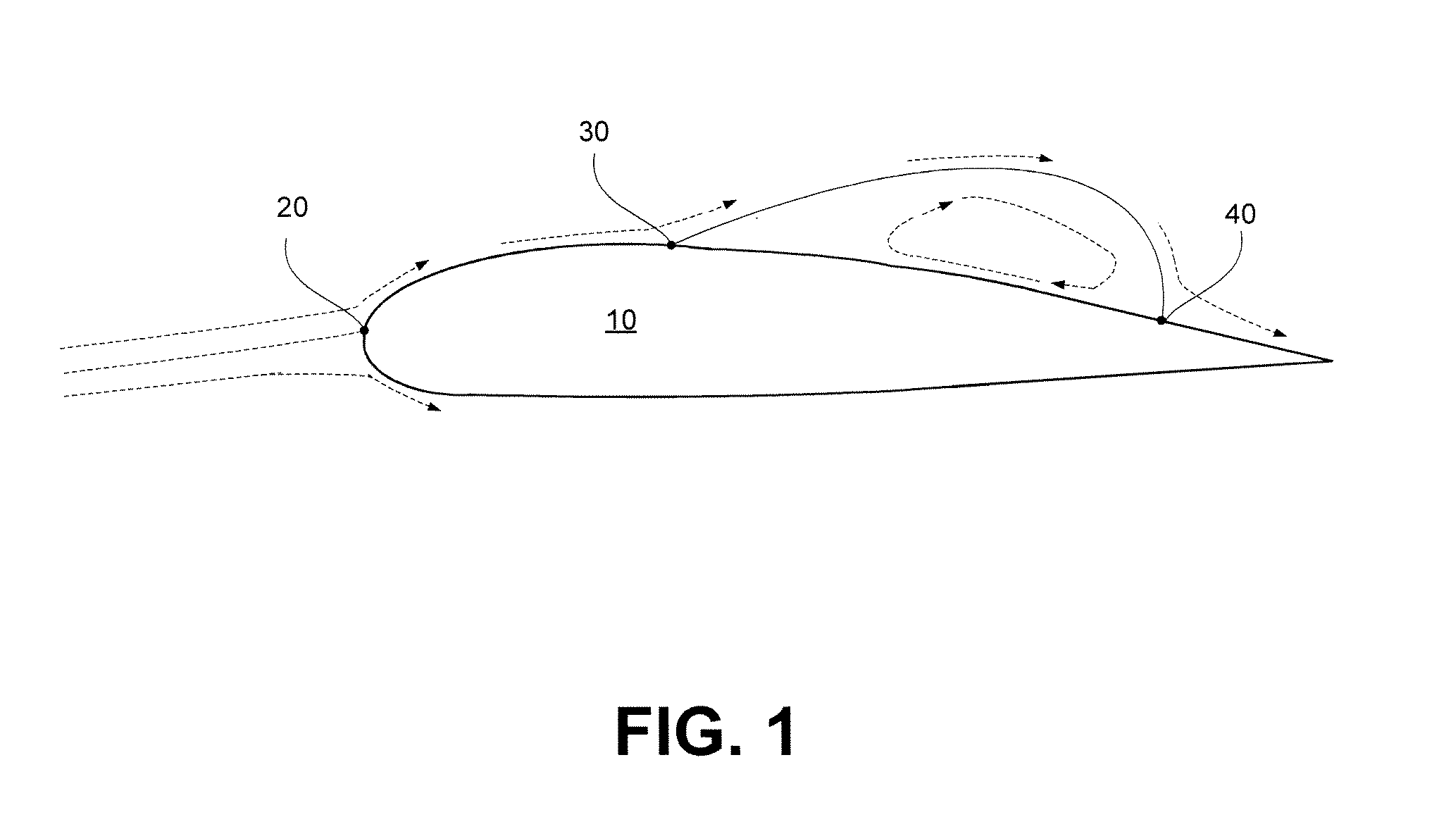
[0026]As used herein, the term “flow bifurcation point” (FBP) means a location on a body surface where the flow attaches to or separates from the body. As shown in the idealized representation of FIG. 1, an airfoil 10 may have several FBPs including the leading...


PUM


Abstract

A method is provided for calculating flow performance characteristics of a body immersed in a fluid under a set of fluid flow conditions. The method comprises providing a geometrical description of a surface of the body and determining the set of fluid flow conditions. The set of fluid flow conditions includes a combination selected from the combination set consisting of angle of attack and leading edge stagnation point location, angle of attack and flow separation point location, and leading edge stagnation point location and flow separation point location. The method further comprises calculating a velocity flow field for the body using a critical point potential flow methodology and calculating flow performance characteristics.

Description

CROSS-REFERENCE TO RELATED APPLICATIONS[0001]This application claims priority to U.S. Provisional Application No. 61 / 078,943, filed Jul. 8, 2008, which is incorporated herein by reference in its entirety.FIELD OF THE INVENTION[0002]The invention relates generally to performance prediction and design of structures immersed in a fluid regime. More particularly, the invention relates to a method of modeling aerodynamic forces and moments that makes use of measured or predicted locations of flow bifurcation points.BACKGROUND OF THE INVENTION[0003]Current design programs use two main methods to achieve the desired aerodynamic characteristics for the airfoil. In the direct method, an iterative procedure is used to successively modify the shape of an airfoil until the desired aerodynamic characteristics are achieved. In the inverse method, the desired aerodynamic characteristics are specified and the airfoil shape that meets these objectives is determined.[0004]The set of governing equatio...

Claims


Application Information

Patent Timeline
IPC IPC(8): G06F17/10
CPCG06F2217/16G06F17/5009G06F30/20G06F2111/10
Inventor MANGALAM, SIVA M.MANGALAM, ARUN
Owner TAO OF SYST INTEGRATION
Why Eureka
Try Eureka