Magnetic cylinder head washer removal tool

a technology for removing tools and cylinder heads, which is applied in the field of hand tools, can solve the problems of difficult for mechanics to access the washers located on each cylinder head stud, the washer is rather small and difficult to manipulate, and the parts are somewhat inaccessible, so as to achieve the effect of difficult manipulation

Inactive Publication Date: 2010-02-18
BRANON TIMOTHY J
View PDF9 Cites 9 Cited by
  • Summary
  • Abstract
  • Description
  • Claims
  • Application Information

AI Technical Summary

Benefits of technology

[0007]As discussed in the Background Information, it has proven to be difficult for mechanics to access the washers located on each cylinder head stud when performing a valve job on an automobile engine. Part of the difficulty is that the washer is rather small and difficult to manipulate and, these washers are located in a very close-fitted recess which makes the parts somewhat inaccessible. The present invention, a magnetic cylinder head washer removal tool, provides for easy removal of these washers. The removal tool includes a cylindrical body having a handle portion and a washer removal end opposite the handle. The cylindrical body includes a central bore that extends the axial length of the body. The removal end includes an end surface having at least one embedded magnet member and defines a pickup surface for use in attracting and securing the easy removal of automotive cylinder head stud washers and automotive cylinder head valve spring spacers valve from the cylinder head.

Problems solved by technology

As discussed in the Background Information, it has proven to be difficult for mechanics to access the washers located on each cylinder head stud when performing a valve job on an automobile engine.
Part of the difficulty is that the washer is rather small and difficult to manipulate and, these washers are located in a very close-fitted recess which makes the parts somewhat inaccessible.

Method used


Image

  • Magnetic cylinder head washer removal tool
  • Magnetic cylinder head washer removal tool
  • Magnetic cylinder head washer removal tool

Examples


Embodiment Construction

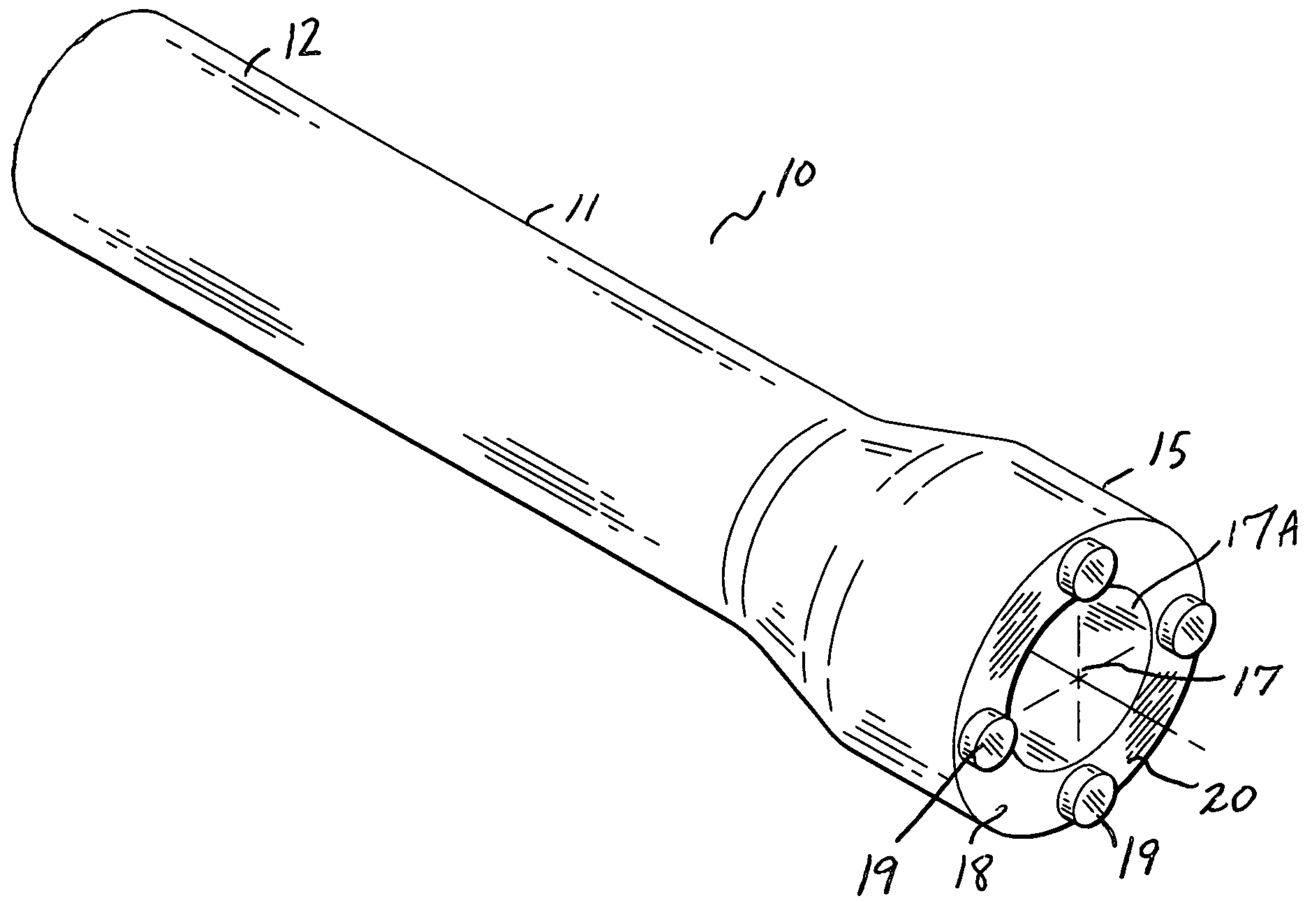
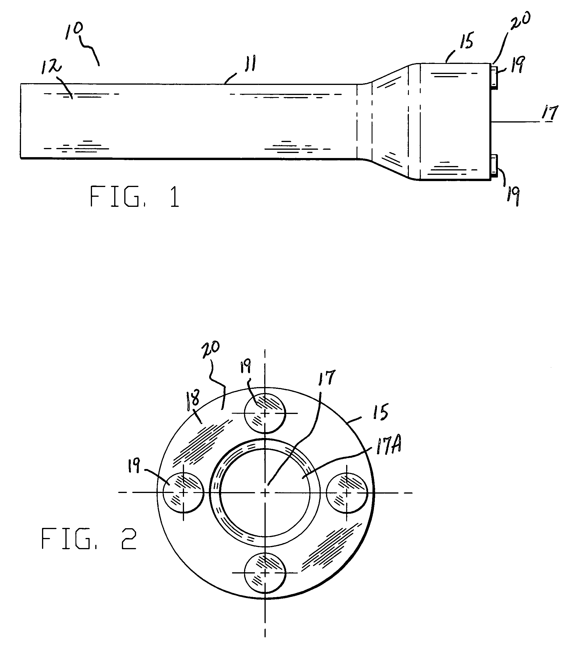
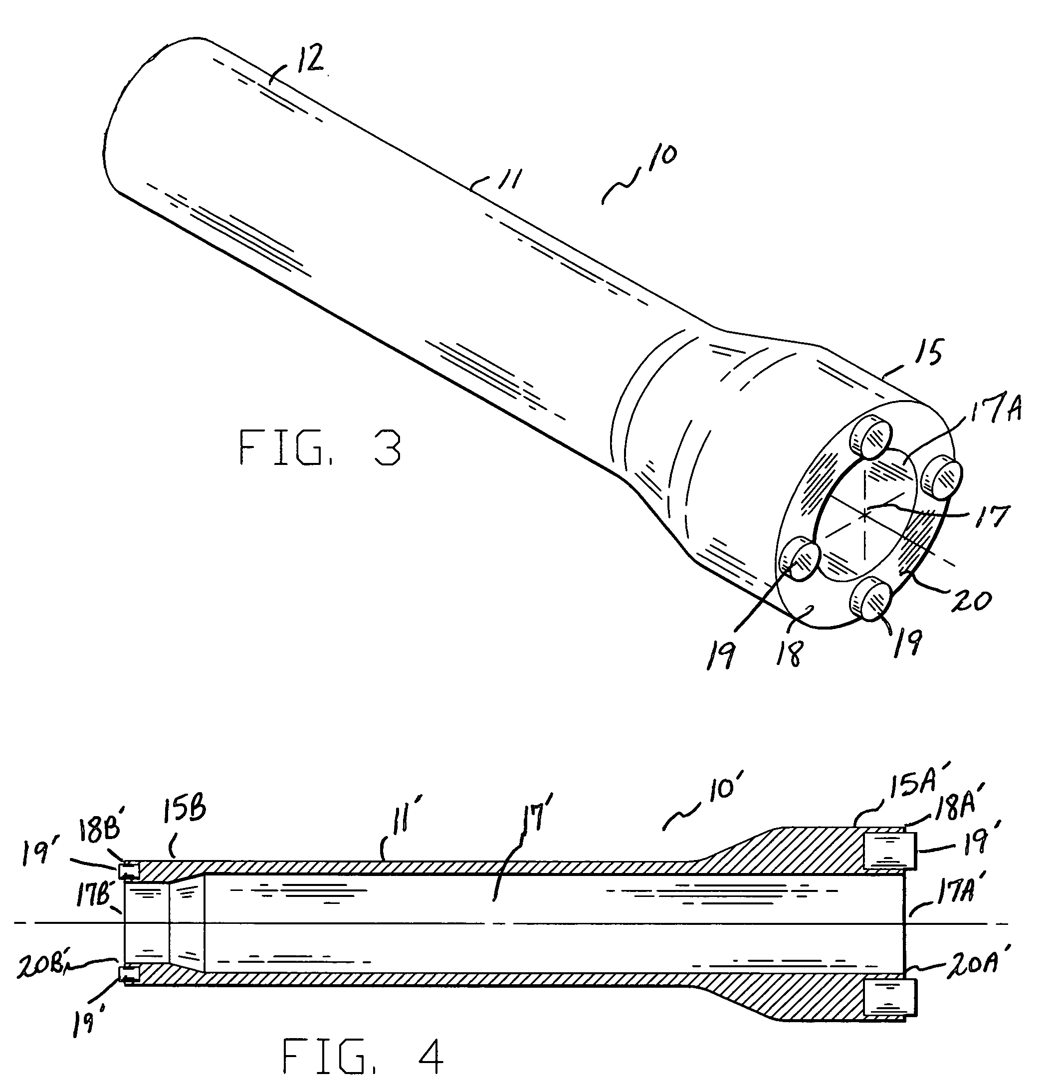
[0012]In accordance with the present invention, a magnetic cylinder head washer removal tool is disclosed. The removal tool of the present invention is directed to a small, compact tool for enabling the easy removal of automotive cylinder head stud washers and automotive cylinder head valve spring spacers. In the broadest context, the removal tool of the present invention consist of components configured and correlated with respect to each other so as to attain the desired objective.

[0013]FIGS. 1-3 illustrate a magnetic cylinder head washer removal tool 10 made in accordance with the present invention. The removal tool 10 generally includes a cylindrical body 11 having a handle 12 at one end and a distal end 15 opposite the handle 12. As will be described, the distal end 15 designed to enable the easy removal of automotive cylinder head stud washers and automotive cylinder head valve spring spacers from the cylinder head in very close-fitted, difficult to access locations. As best s...


PUM

PropertyMeasurementUnit
diameteraaaaaaaaaa
axial lengthaaaaaaaaaa
strengthaaaaaaaaaa

Abstract

A removal tool for removing washers located on each cylinder head stud when performing a valve job on an automobile engine. The removal tool includes a cylindrical body having a handle portion and a washer removal end opposite the handle. The cylindrical body includes a central bore that extends the axial length of the body. The removal end includes an end surface having at least one embedded magnet member and defines a pickup surface for use in attracting and securing the easy removal of automotive cylinder head stud washers and automotive cylinder head valve spring spacers valve from the cylinder head.

Description

CROSS REFERENCES TO RELATED APPLICATIONS[0001]U.S. Provisional Application for Patent No. 61 / 188,913, filed Sep. 8, 2008, with title “Magnetic Cylinder Head Washer / Shim Removal Tool” which is hereby incorporated by reference. Applicant claim priority pursuant to 35 U.S.C. Par. 119(e)(i).STATEMENT AS TO RIGHTS TO INVENTIONS MADE UNDER FEDERALLY SPONSORED RESEARCH AND DEVELOPMENT[0002]Not applicable.BACKGROUND OF THE INVENTION[0003]1. Field of the Invention[0004]This present invention relates to the field of hand tools and more particularly, to a tool for removal of automotive cylinder head stud washers and automotive cylinder head valve spring spacers.[0005]2. Background Information[0006]The automobile engine “valve job” involves removal of the valve cover and cylinder head, followed by disassembly and removal of each valve from the cylinder head for replacement or repair. This known process includes the removal of a washer from each cylinder head stud. It has proven to be very chall...

Claims


Application Information

Patent Timeline
Patent Type & Authority Applications(United States)
IPC IPC(8): B25B27/00
CPCB25B11/002B25B27/0035Y10T29/5182Y10T29/53943Y10T29/4561Y10T29/53596
Inventor BRANON, TIMOTHY J.
Owner BRANON TIMOTHY J
Why Eureka
Try Eureka