
Wall panel joint apparatus and system using same

a wall panel joint and wall panel technology, applied in the field of wall panel joints and systems, can solve problems such as system problems, water damage, water damage, and/or lack of venting capability, and achieve the effect of optimizing ventilation and minimizing water entry

Inactive Publication Date: 2010-02-18
LYMO CONSTR
View PDF25 Cites 47 Cited by
  • Summary
  • Abstract
  • Description
  • Claims
  • Application Information

AI Technical Summary

Benefits of technology

[0007]In contrast to the above-described wall panel systems, the instant system has a symmetric panel structure with a wall panel joint having a pair of perimeter clips and at least two filler strips defining at least one chamber in addition to a wall cavity. The chamber provides for pressure equalization by increasing the air pressure within the chamber until it equals the applied wind pressure. Furthermore, the configuration of the flange portion of the outer strip flange projecting higher like the mounting flange results in blocking water. When the pressures are equal, water cannot enter the chamber. This state is attained quickly. Thus, the wall panel joints allow the wall panel system to attain optimal ventilation within the system, but prevent and minimize water entry. Furthermore, the system in addition to the pressure equalization chamber provides an internal gutter system and allows for thermal movement between adjacent wall panel units.
[0010]A pair of filler strips is associated with a pair of perimeter clips of the plurality of perimeter clips. The filler strips with the pair of perimeter clips define a wall panel joint. Each of the filler strips has a pair of receiving edges. Each of the filler strips extends between adjacent perimeter clips with a first receiving edge received in a pocket of one of the perimeter clips and the second receiving edge received in a pocket of the other perimeter clip. The pair of filler strips defines a chamber interposed between the adjacent perimeter clips and the filler strip for allowing pressure equalization while minimizing water entry into the wall cavity.
[0020]In an embodiment, the perimeter clip has at least three strip flanges and at least three pockets defined by the at least three strip flanges and the body. There are at least three filler strips. Each of the filler strips has a pair of receiving edges. Each of the filler strips extends between adjacent perimeter clips with a first receiving edge received in a pocket of one of the perimeter clips and the second receiving edge received in a pocket of the other perimeter clip. There are at least two chambers wherein each chamber is interposed between the adjacent perimeter clips and a pair of the at least three filler strips for allowing pressure equalization while minimizing water entry.
[0021]In an arrangement, the at least one pair of strip flanges extending from the body includes an outer strip flange, a middle strip flange, and an inner strip flange. The outer strip flange defines a “U” shaped outer pocket. The middle strip flange and the inner strip flange define a “U” shaped inner pocket. The pair of filler strips includes an outer filler strip extending between the “U” shaped outer pocket of an adjacent perimeter clip and an inner filler strip extending between the “U” shaped inner pocket of the adjacent perimeter clip. The outer filler strip and the inner filler strip define a chamber interposed between the adjacent perimeter clips and the filler strip for allowing pressure equalization while minimizing water entry.
[0023]In an embodiment, a wall panel joint includes a pair of perimeter clips and a pair of filler strips. Each perimeter clip includes a body, a panel flange extending from the body, and at least a pair of strip flanges. The panel flange is adapted to engage with one of the mounting flanges of one of the wall panels. The strip flanges and the body define at least a pair of pockets. Each of the filler strips has a pair of receiving edges. Each of the filler strips extends between adjacent perimeter clips with a first receiving edge received in a pocket of one of the perimeter clips and the second receiving edge received in a pocket of the other perimeter clip. The pair of filler strips defines a chamber interposed between the adjacent perimeter clips and the filler strips for allowing pressure equalization while minimizing water entry.
[0027]A pair of filler strips is positioned with at least one of the perimeter clips of at least one of the wall panel units. The steps of mounting of a plurality of wall securing devices, mounting a plurality of attachment clips, positioning the perimeter clip and the securing the plurality of attachment clips are repeated until the wall panel system is completely secured to the building with a wall panel joint that has at least one chamber interposed between the adjacent perimeter clips and the filler strips allowing pressure equalization while minimizing water entry.

Problems solved by technology

However, the lack of permeability / venting to either water vapor or air makes this system problematic.
However, these systems allow water to penetrate, causing water damage which is also problematic.
Unfortunately, there are deficiencies in conventional wall panel systems that lead to water damage and / or lack of venting capability.
Furthermore, the configuration of the flange portion of the outer strip flange projecting higher like the mounting flange results in blocking water.

Method used


Image

  • Wall panel joint apparatus and system using same
  • Wall panel joint apparatus and system using same
  • Wall panel joint apparatus and system using same

Examples


examples

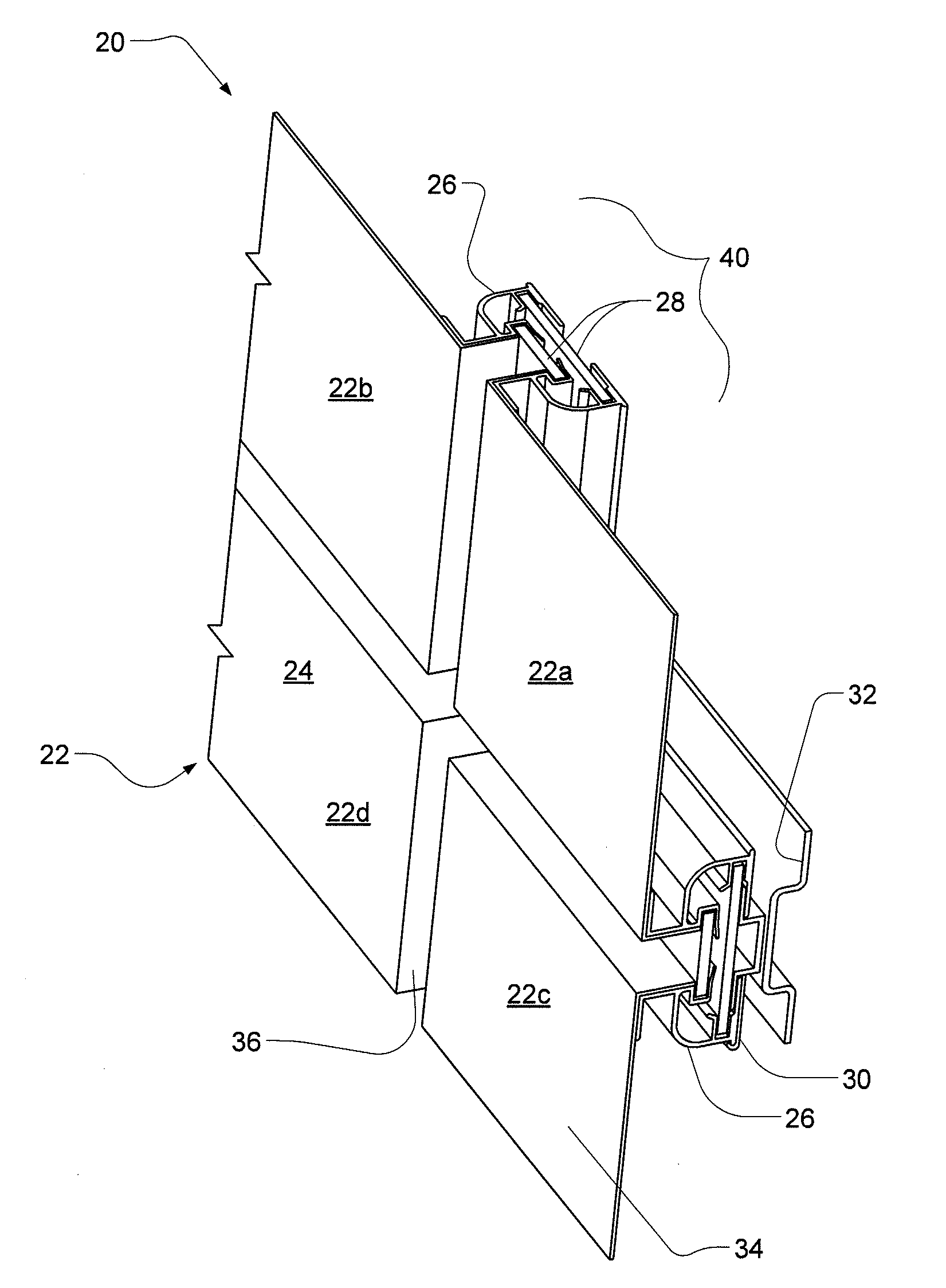
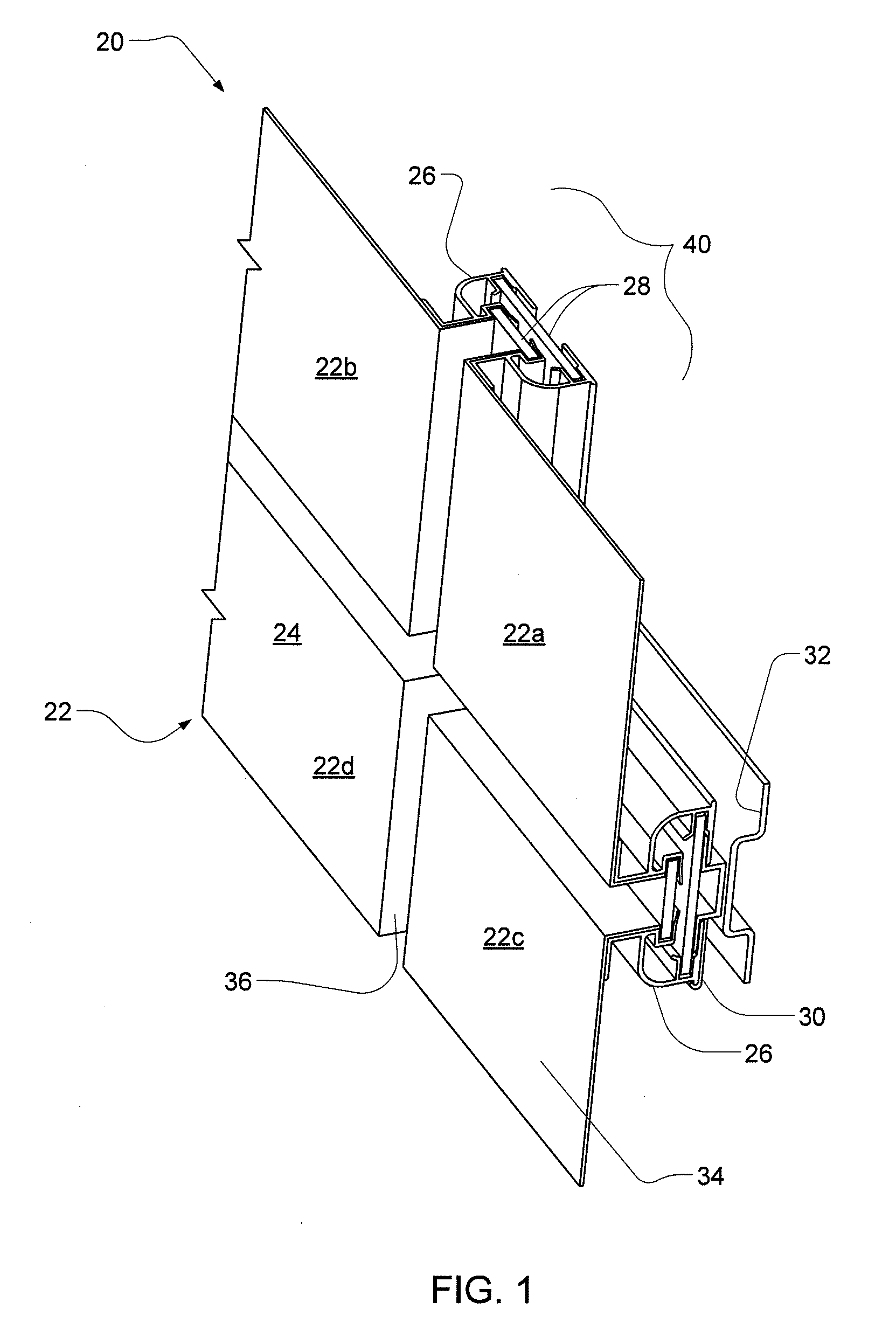
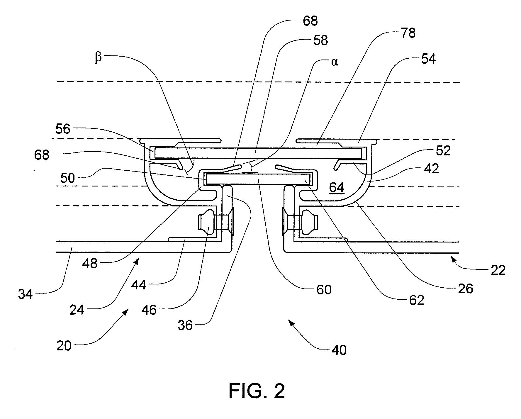
[0081]Referring again to FIGS. 2 and 3, the features in this exemplary embodiment of the horizontal and vertical joints work to prevent water from penetrating into the architectural wall. This is proven by the tests represented in the examples below.

[0082]Air infiltration, water penetration, and structural performance tests of the system installed in a laboratory test chamber were performed. Wall Assembly A was tested on Apr. 8, 2005; Wall Assembly B was tested for water penetration in accordance with ASTM: E 331 on Apr. 22, 2005, and for water penetration in accordance with ASTM: E 331 but modified to monitor air flow as openings were cut in the back-up wall on May 6 and Jun. 7, 2005. The following comments describe the test procedures and results for each wall assembly.

DESCRIPTIONS OF WALL ASSEMBLIES

[0083]WALL ASSEMBLY A—APR. 8, 2005: water penetration air infiltration and structural tests were performed on Wall Assembly A.

[0084]TEST SPECIMEN—DESCRIPTION

[0085]The following wall as...


PUM


Abstract

A wall panel joint apparatus and a system using same is disclosed. The wall panel joint includes a perimeter joint body having a predetermined size and shape. The perimeter joint body floatably attaches to at least two wall panels. Embodiments include where the wall panel joint includes one, two, or more chambers in addition to the wall cavity. The system includes at least two wall panel joints that attach the wall panels to an architectural wall. At the point of intersection of the joints, the joints are mitered. The system also includes a wall attachment device and a means for attaching the joint to the wall attachment device. The system is liquid water impermeable, air permeable, and water vapor permeable system, providing a ventilated, waterproof wall panel attachment joints for use in same.

Description

CROSS REFERENCE TO RELATED APPLICATIONS[0001]The present application is a continuation-in-part application of U.S. patent application Ser. No. 11 / 336,242 filed on Jan. 20, 2006 which claims the benefit of Provisional Patent Application Ser. No. 60 / 645,101 filed Jan. 20, 2005 and Provisional Patent Application Ser. No. 60 / 655,370 filed Feb. 23, 2005, which are incorporated herein by reference.TECHNICAL FIELD[0002]The present invention relates to wall panel joints and systems for wall panel application.BACKGROUND INFORMATION[0003]Architectural panel has been in use for many years. All architectural panel systems can be classified into two major categories, namely, “face-sealed” and “vented rainscreen” systems.[0004]Face-sealed systems include all systems with joinery that make use of sealant in the joinery whereby the system is substantially impermeable to either water or air. Achieving complete face seal is the very basis of all face seal systems. Sealant can be caulking, gasket, or ...

Claims


Application Information

Patent Timeline
IPC IPC(8): E04B2/00E04B1/00
CPCE04F13/0889E04F13/007E04F17/00
Inventor LYNCH, DANTAING, KONG K.
Owner LYMO CONSTR
Features
  • Generate Ideas
  • Intellectual Property
  • Life Sciences
  • Materials
  • Tech Scout
  • Unparalleled Data Quality
  • Higher Quality Content
  • 60% Fewer Hallucinations
Learn More