Workstation with a multiple-face parts support, and a method of controlling such a workstation
Active Publication Date: 2010-02-18
ABB FRANS
View PDF2 Cites 3 Cited by
Summary
Abstract
Description
Claims
Application Information
AI Technical Summary
This helps you quickly interpret patents by identifying the three key elements:
Problems solved by technology
Method used
Benefits of technology
Benefits of technology
[0008]Thus, parts are positioned in the workstation by the handling robot, and the operational units can operate simultaneously on the support as positioned by the handling robot. It is then possible to perform operations concurrently and to compensate for variations in dimensions between series of parts by modifying the position and the inclination of the support in the workstation.
[0010]This embodiment is particularly advantageous since it limits any risk of interference between the operational units that are co-operating simultaneously with the support.
Problems solved by technology
The users of such workstations generally need to maximize their profitability, i.e. to make maximum use of the workstations and the elements making them up, and they also have flexibility requirements for workstations to be easily be adapted to different types of part, different rates of throughput, and to modifications in the manufacturing process, it nevertheless being understood that this need for flexibility must not be satisfied to the detriment of profitability.
Method used
Image
Click on the blue label to locate the original text in one second.
Reading with bidirectional positioning of images and text.
Examples
first embodiment
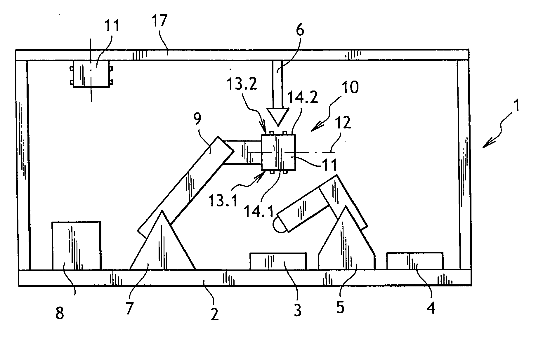
[0023]With reference to FIG. 1, the workstation in accordance with a first embodiment is for performing final welding of a part comprising two preassembled portions.
[0024]The workstation, given overall reference 1, comprises a base 2 having mounted thereon a parts-delivery conveyor 3, a parts-removal conveyor 4, a first operational unit 5, a second operational unit 6, and a multiple-axis handling robot 7. The conveyors 3 and 4, the operational units 5 and 6, and the handling robot 7 are connected to a control unit 8 comprising a computer system executing a program arranged to cause the above-mentioned elements constituting the workstation 1 to operate in coordinated manner.
[0025]The base 2 comprises, in conventional manner, a soleplate that rests on the ground and that carries a frame and that is surrounded by a protective perimeter that is not visible in FIG. 1 (wire mesh, walls, . . . ). The soleplate enables the workstation 1 to be fastened to the ground and it includes passages ...
second embodiment
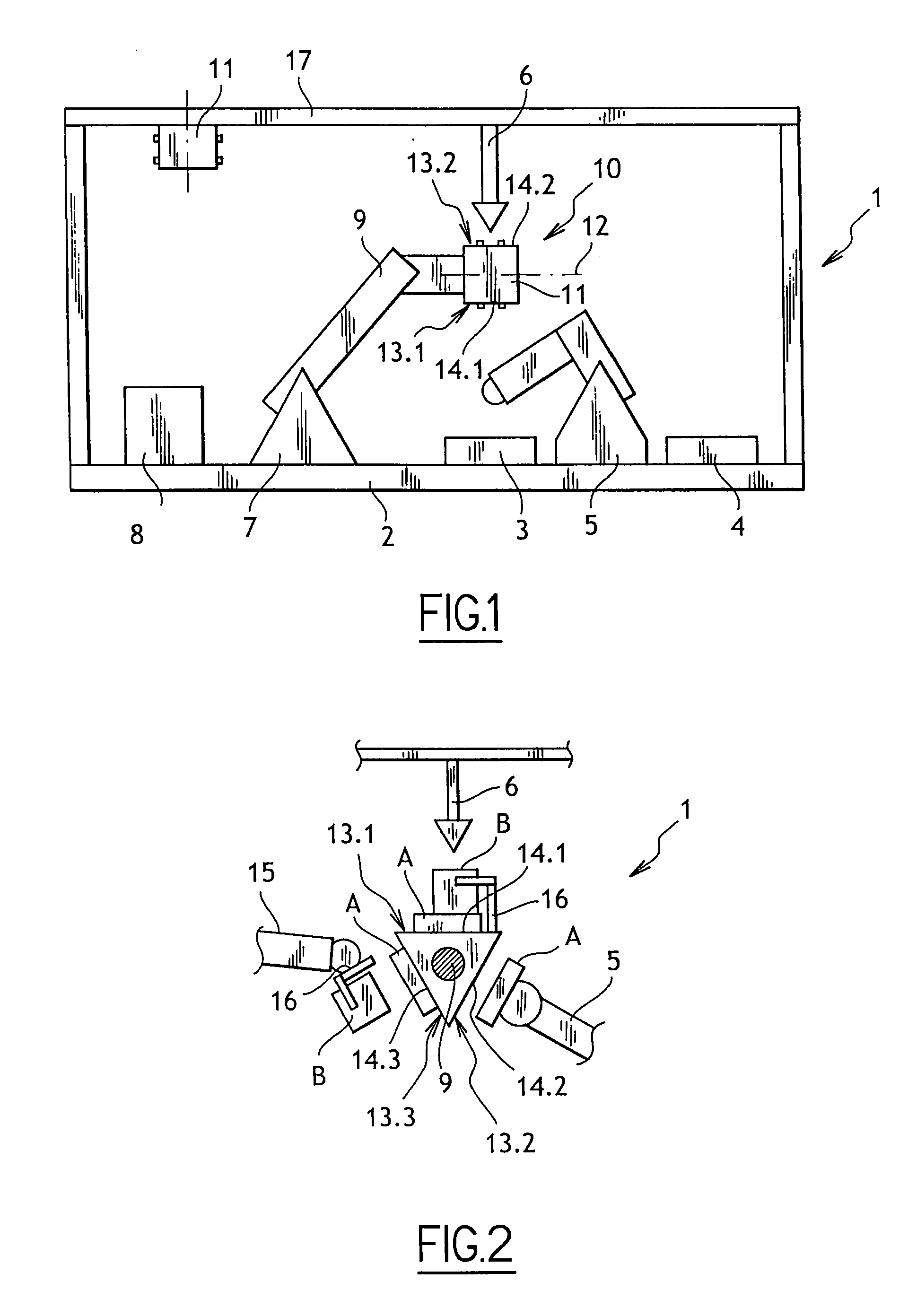
[0039]In the description below of a second embodiment as shown in FIG. 2, elements that are identical or analogous to those described above are given the same numerical references.
[0040]The workstation 1 of the second embodiment is generally identical to that of the first embodiment, i.e. it comprises a loading / unloading robot 5, a welding head 6, and a handling robot 7, of which only the arm 9 is shown (in cross-section in FIG. 2).
[0041]Nevertheless, the workstation 1 is now arranged to weld together a part of a first type A and a part of a second type B, which parts are brought separately to the workstation 1 by transport means that are themselves known, such as conveyors or robots.
[0042]The loading / unloading robot 5 is controlled to load parts of the first type A on the support 10 and to unload from the support 10 welded assemblies as formed by assembling a part of the first type A with a part of the second type B.
[0043]The workstation 1 has an additional loading robot 15 control...
PUM
Abstract
The invention relates to a robotic workstation (1), comprising at least one multiple-axis parts-handling robot (7) having an arm (9) with a free end that is provided with a parts support (10), and first and second operational units (5, 6) for co-operating functionally with the support, and wherein the support comprises a body (11) provided with locations (14) for receiving parts, said locations being arranged so that each of them is accessible simultaneously by one of the operational units. The invention also provides a method of controlling the station.
Description
BACKGROUND OF THE INVENTION[0001]1. Field of the Invention[0002]The present invention relates to a workstation and to a method of controlling such a workstation. A workstation of this type can be used in fabricating bodywork parts for motor vehicles.[0003]2. Brief Discussion of the Related Art[0004]A workstation generally comprises a base having fastened thereto at least a parts-handling robot and an operational unit for performing at least one operation on the parts, such as an assembly, welding, crimping, or other operation. The handling robot is generally controlled so as to load the parts onto a support that is secured to the base and that is arranged to hold each part in a predetermined position so as to occupy a geometrical position reference for the operation that is performed by the operational unit. Once the operation has been completed, the handling robot takes hold of the part in order to place it outside the workstation.[0005]The users of such workstations generally need...
Claims
Application Information
Patent Timeline
Application Date:The date an application was filed.
Publication Date:The date a patent or application was officially published.
First Publication Date:The earliest publication date of a patent with the same application number.
Issue Date:Publication date of the patent grant document.
PCT Entry Date:The Entry date of PCT National Phase.
Estimated Expiry Date:The statutory expiry date of a patent right according to the Patent Law, and it is the longest term of protection that the patent right can achieve without the termination of the patent right due to other reasons(Term extension factor has been taken into account ).
Invalid Date:Actual expiry date is based on effective date or publication date of legal transaction data of invalid patent.

