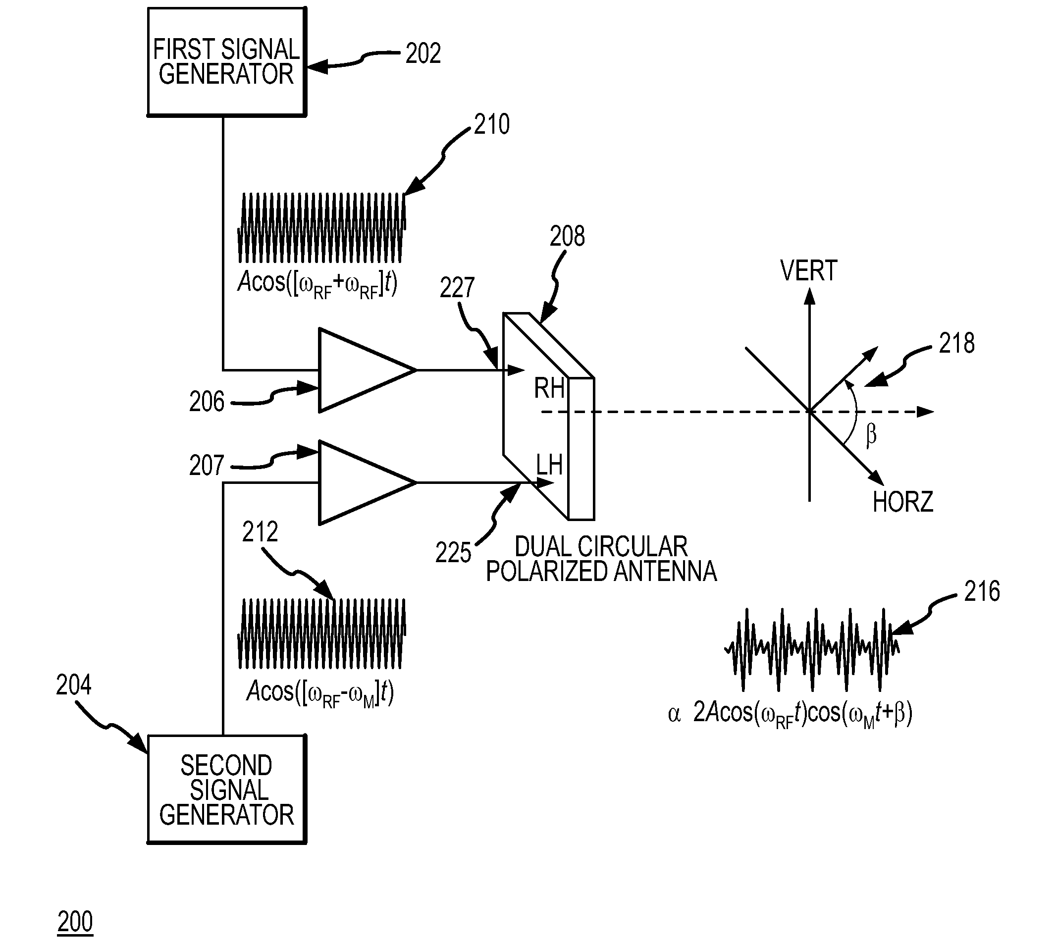
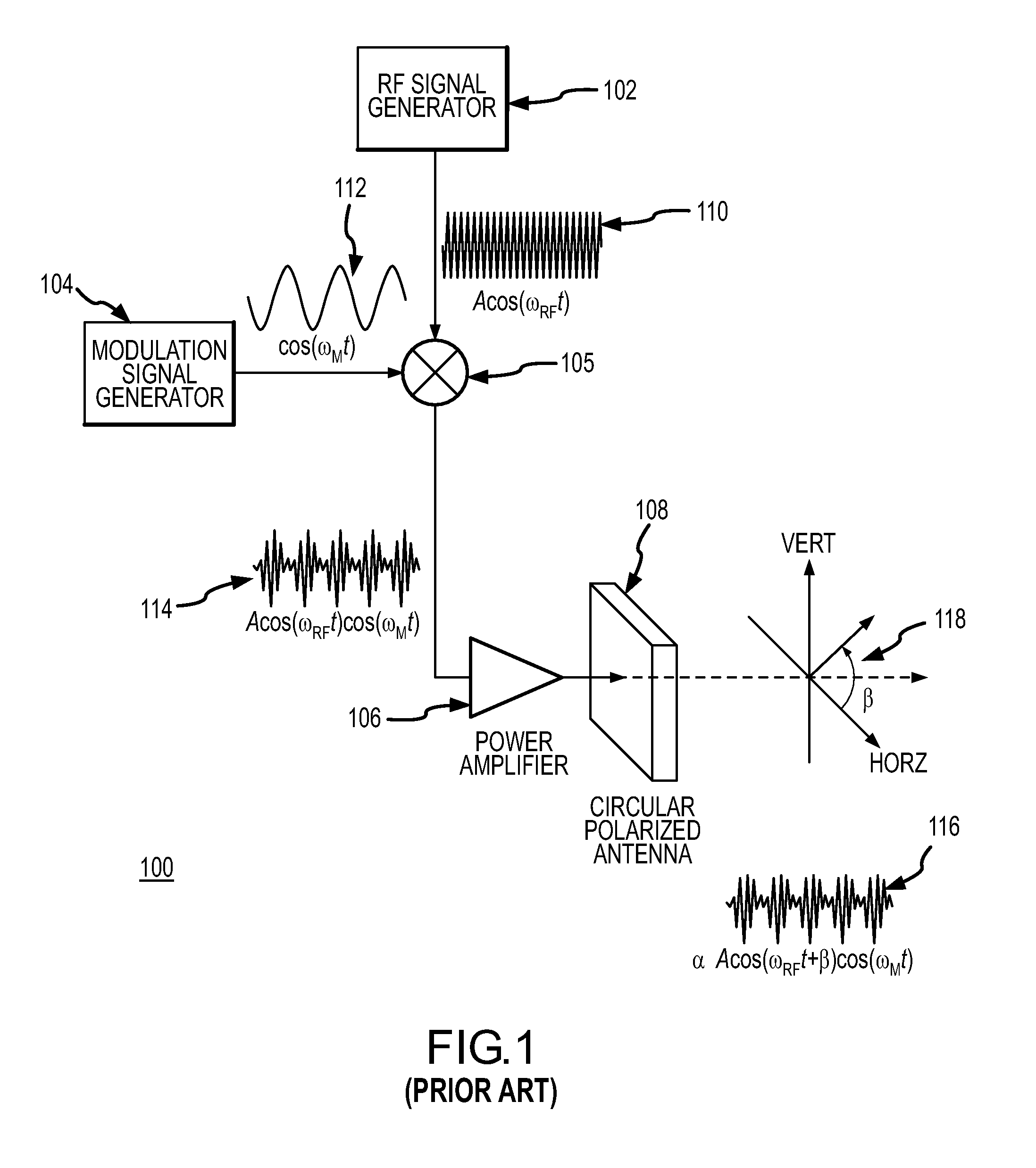
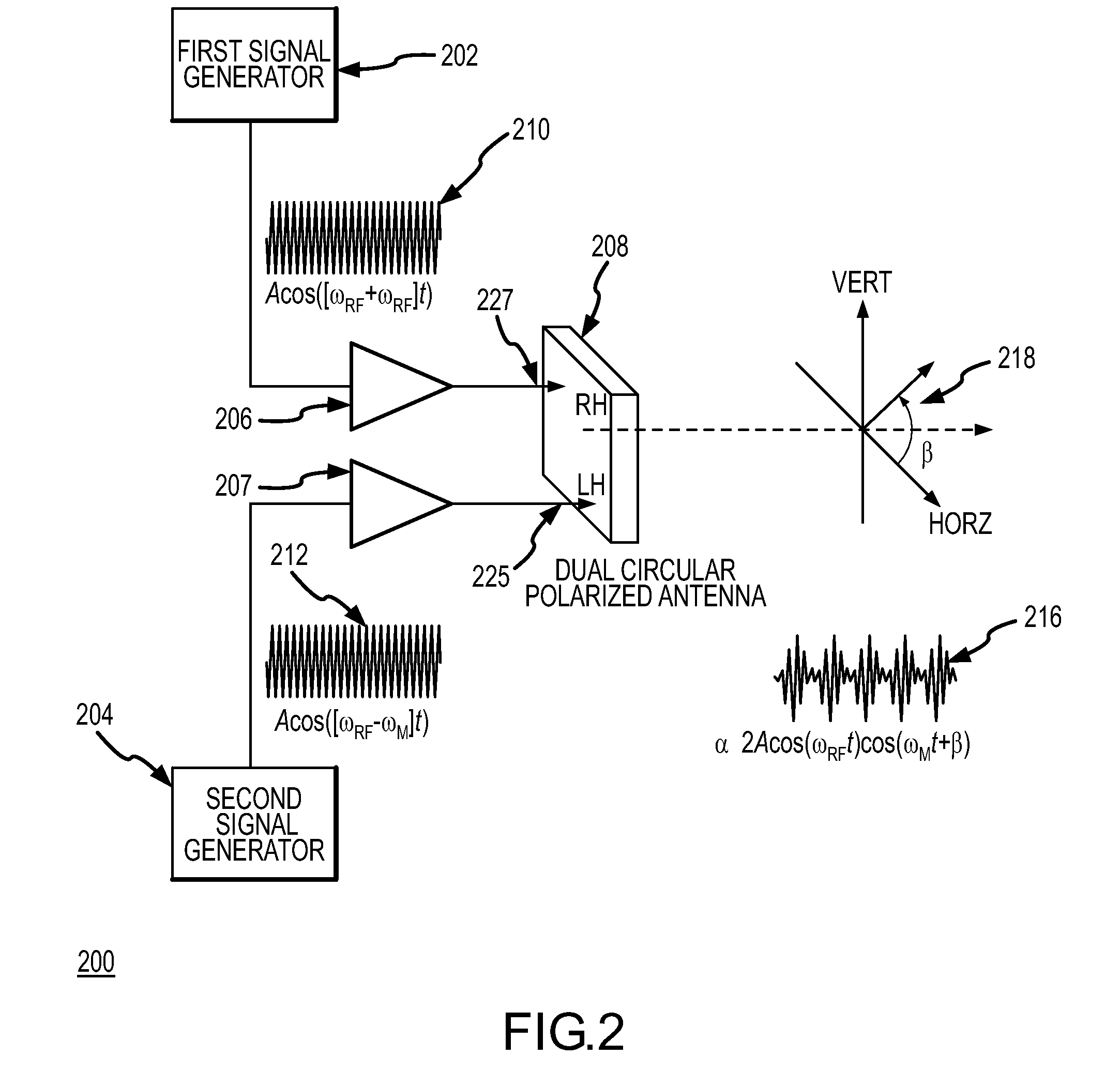
RF waveform modulation apparatus and method
a waveform modulation and waveform technology, applied in the field of electromagnetic modulation apparatus and method, can solve the problems of limiting the range, efficiency and effectiveness of directed energy weapons, and the average power of modulated signals is significantly less
- Summary
- Abstract
- Description
- Claims
- Application Information
AI Technical Summary
Benefits of technology
Problems solved by technology
Method used
Image

Examples
Embodiment Construction
[0012]The following representative descriptions of the present invention generally relate to exemplary embodiments and the inventor's conception of the best mode, and are not intended to limit the scope, applicability or configuration of the invention in any way. Rather, the following description is intended to provide convenient illustrations for implementing various embodiments of the invention. As will become apparent, changes may be made in the function and / or arrangement of any of the elements described in the disclosed exemplary embodiments without departing from the spirit and scope of the invention.
[0013]Various representative implementations of the present invention may be applied to any signal modulation apparatus. For example, certain representative implementations may include phased array directed-energy units used in applications such as anti-missile defense of an aircraft, fixed target, waterborne vessel, and / or the like.
[0014]A detailed description of an exemplary app...
PUM
 Abstract
Description
Claims
Application Information