Low profile rear cavity ring gap one-point short circuit round polarization antenna

A circularly polarized antenna and circular ring technology, applied in slot antennas, circuits, radiating element structures and other directions, can solve the problems of large volume and inability to plane integration, low gain axis ratio, low axial ratio bandwidth, and inability to plane integration, etc. Excellent radiation characteristics, cost reduction, and volume reduction effects

Inactive Publication Date: 2008-04-30
HANGZHOU DIANZI UNIV
View PDF0 Cites 26 Cited by
  • Summary
  • Abstract
  • Description
  • Claims
  • Application Information

AI Technical Summary

Problems solved by technology

Compared with the previous cavity-backed circularly polarized antenna, this implementation method is greatly reduced in size, but its processing cost is still high, and it cannot be integrated in a plane; the helical antenna is mainly used in space applications o

Method used


Image

  • Low profile rear cavity ring gap one-point short circuit round polarization antenna
  • Low profile rear cavity ring gap one-point short circuit round polarization antenna
  • Low profile rear cavity ring gap one-point short circuit round polarization antenna

Examples


Embodiment Construction

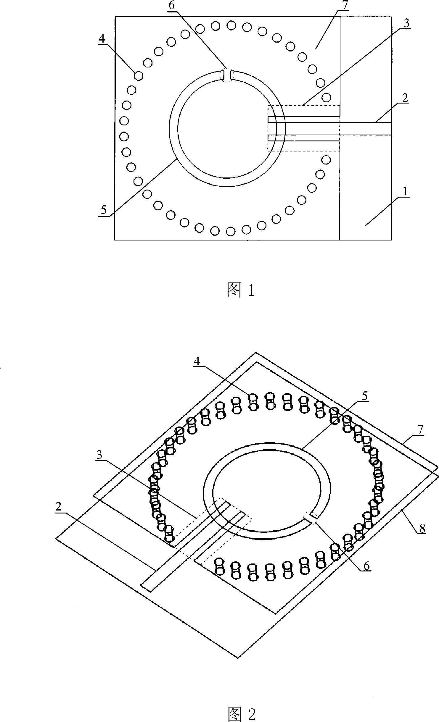
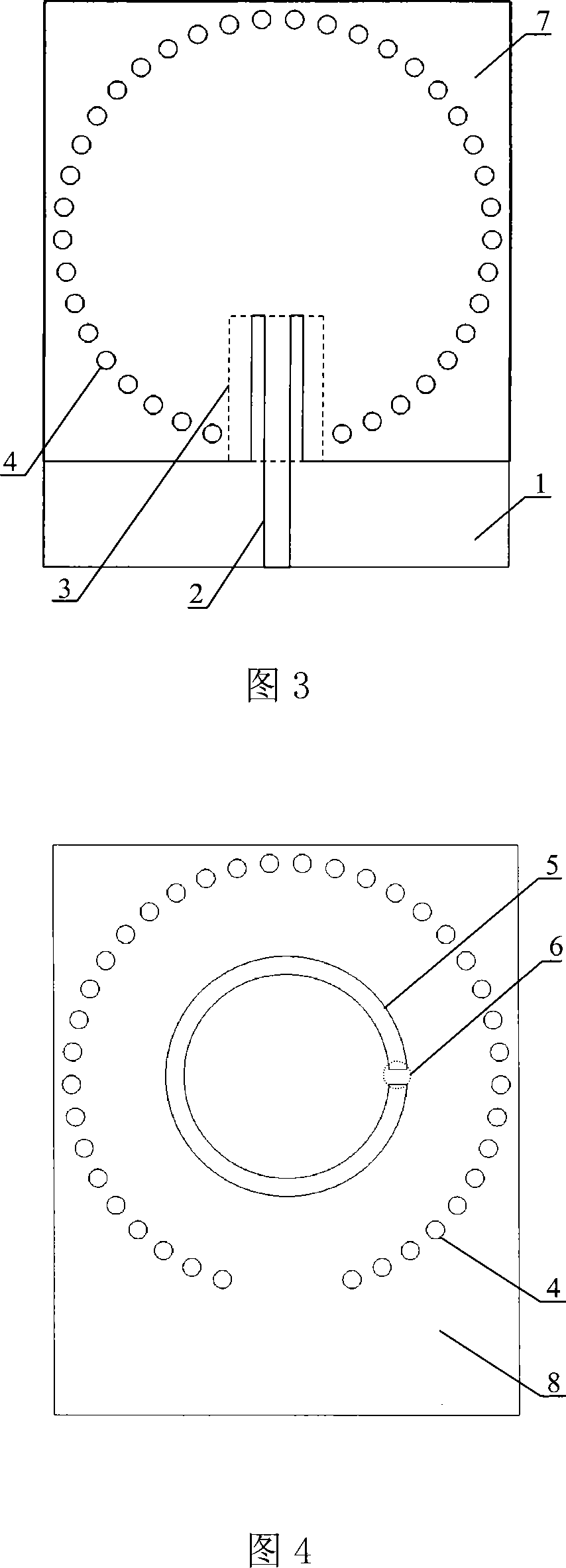
[0021] As shown in Figures 1 and 2, the low-profile cavity-backed annular gap one-point short-circuit circularly polarized antenna includes a Rogers5880 dielectric substrate 1 with a thickness of 0.5 mm, and the two sides of the dielectric substrate 1 are coated with metal layers, which are respectively the upper metal layer 7 And the lower metal layer 8, wherein the lower metal layer 8 is used as the formation layer. As shown in Figure 3, the upper metal layer 7 is etched with a microstrip line 2 for feeding and a coplanar waveguide transmission line 3 (the dotted box includes the part), and the coplanar waveguide transmission line 3 is a common ground coplanar waveguide structure, and the middle metal strip Extend outward, as the microstrip line 2. The length and width of the microstrip line 2 are 4 mm and 1.45 mm respectively, and the two air gaps of the coplanar waveguide transmission line 3 both have a width of 0.7 mm and a length of 8.2 mm. A through hole with a diamete...


PUM


Abstract

The invention relates to a one-point short-circuit circularly polarized antenna with a low-profile cavity-backed annular slot. The existing cavity-backed circularly polarized antenna based on one-point short-circuit of the annular slot has complex structure, large volume, inability to planar integration, and high cost. In the present invention, a metal layer is plated on both sides of the dielectric substrate, and the upper metal layer is etched with a microstrip line for power feeding and a common ground coplanar waveguide transmission line, and the middle metal strip of the coplanar waveguide transmission line extends outwards as a microstrip line . Through the upper metal layer, the dielectric substrate and the lower metal layer, a plurality of metallized through holes arranged in a circle are opened to form a cavity, and the coplanar waveguide transmission line extends into the cavity. The lower metal layer is etched with a circular radiation slit with a short circuit in the area corresponding to the cavity. Compared with the conventional cavity-backed circularly polarized antenna composed of a metal cavity, the present invention is manufactured by common PCB technology, has low manufacturing cost, can be seamlessly integrated with a microstrip circuit, and improves system integration.

Description

technical field [0001] The invention belongs to the field of microwave technology, and relates to a low-profile cavity-backed annular gap one-point short-circuit circularly polarized antenna based on substrate integrated waveguide technology, which can be used as a radio frequency transceiver front-end antenna and is widely used in mobile communications, satellite communications, Radar and other wireless communication systems are used to solve the polarization mismatch problem caused by the Faraday electromagnetic rotation effect, and can also play a role in suppressing rain and fog interference and anti-multipath reflection. Background technique [0002] As a key component of a communication system, antennas are widely used in wireless communication occasions. Due to the Faraday rotation effect of radio wave propagation in space and the uncertainty of the position of the receiving antenna in mobile communication, if a traditional single-polarized antenna is used as the tran...

Claims


Application Information

Patent Timeline
IPC IPC(8): H01Q1/38H01Q13/10H01Q13/06
Inventor 罗国清孙玲玲
Owner HANGZHOU DIANZI UNIV
Why Eureka
Try Eureka