Spiral cylindrical ceramic circular polarized antenna

a ceramic and circular polarized antenna technology, applied in the field of antennas, can solve the problems of wasting the most radiation energy, the efficiency and response of the antenna to be worse than expected, and achieve the effect of reducing induction noise and improving wave filtering

Inactive Publication Date: 2006-02-23
FENG I PENG +1
View PDF6 Cites 27 Cited by
  • Summary
  • Abstract
  • Description
  • Claims
  • Application Information

AI Technical Summary

Benefits of technology

[0005] The present invention is a GPS antenna comprising a body made of microwave ceramic material, and spiral radiation metallic electrodes to form a rotation loop structure that can reduce induction noise and serve as a better wave filter, and with right circular polarized all direction radiation pattern, and ceramic ground plane ...

Problems solved by technology

Most of the energy emitted and received by radio wave for conventional microwave antenna hand-held electronic devices or other communication products will be affected by hand, head, or ...

Method used


Image

  • Spiral cylindrical ceramic circular polarized antenna
  • Spiral cylindrical ceramic circular polarized antenna
  • Spiral cylindrical ceramic circular polarized antenna

Examples


Embodiment Construction

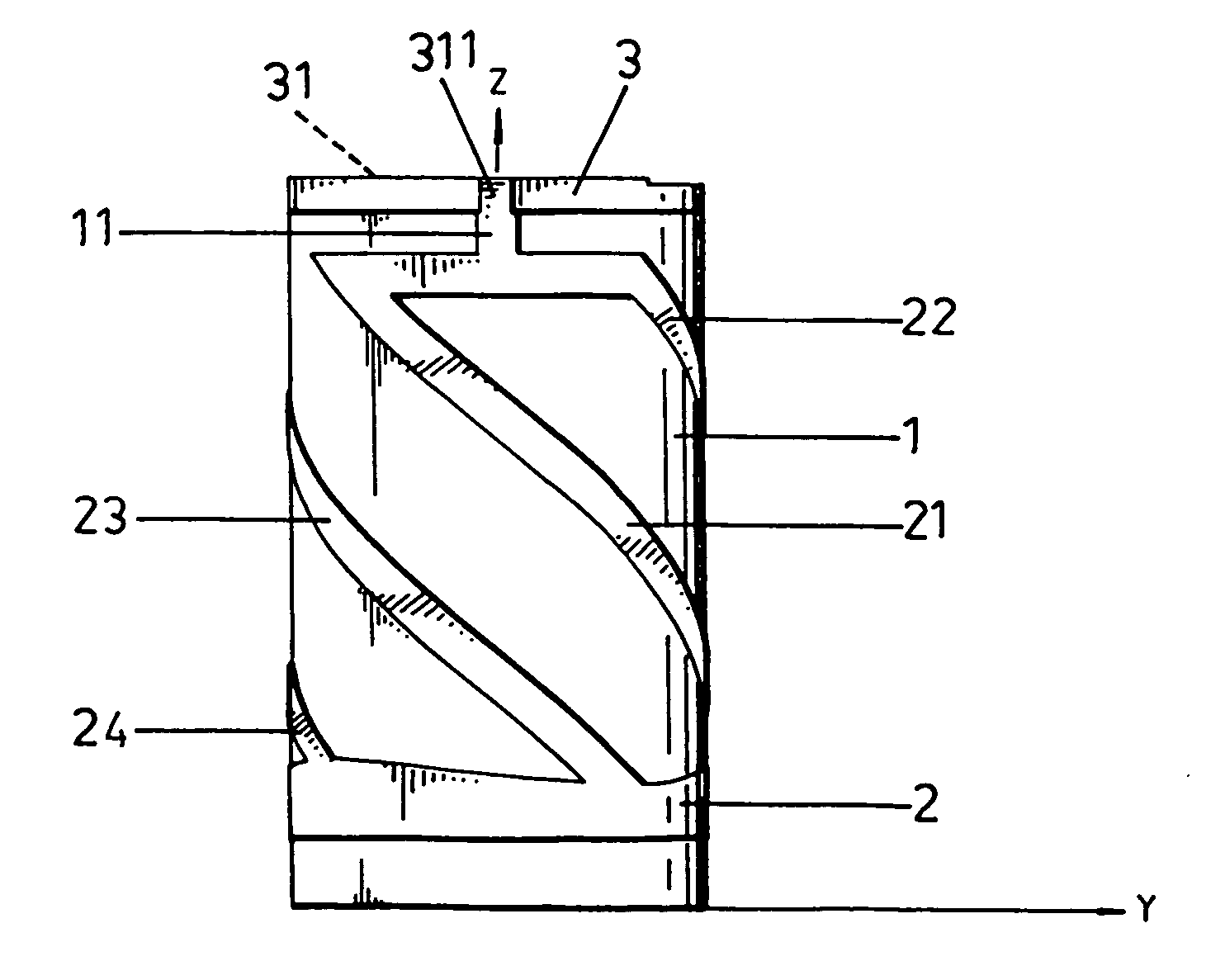
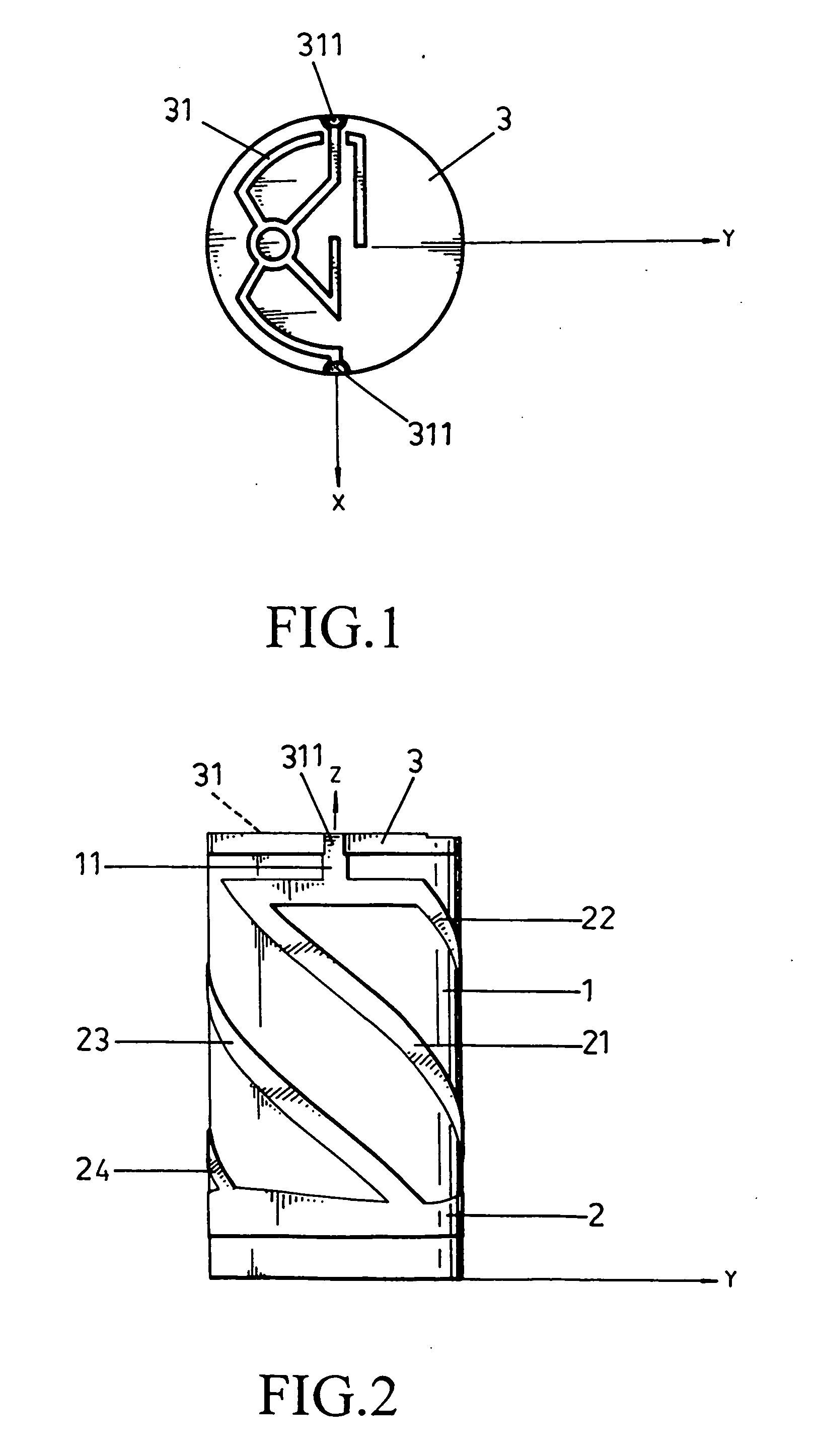
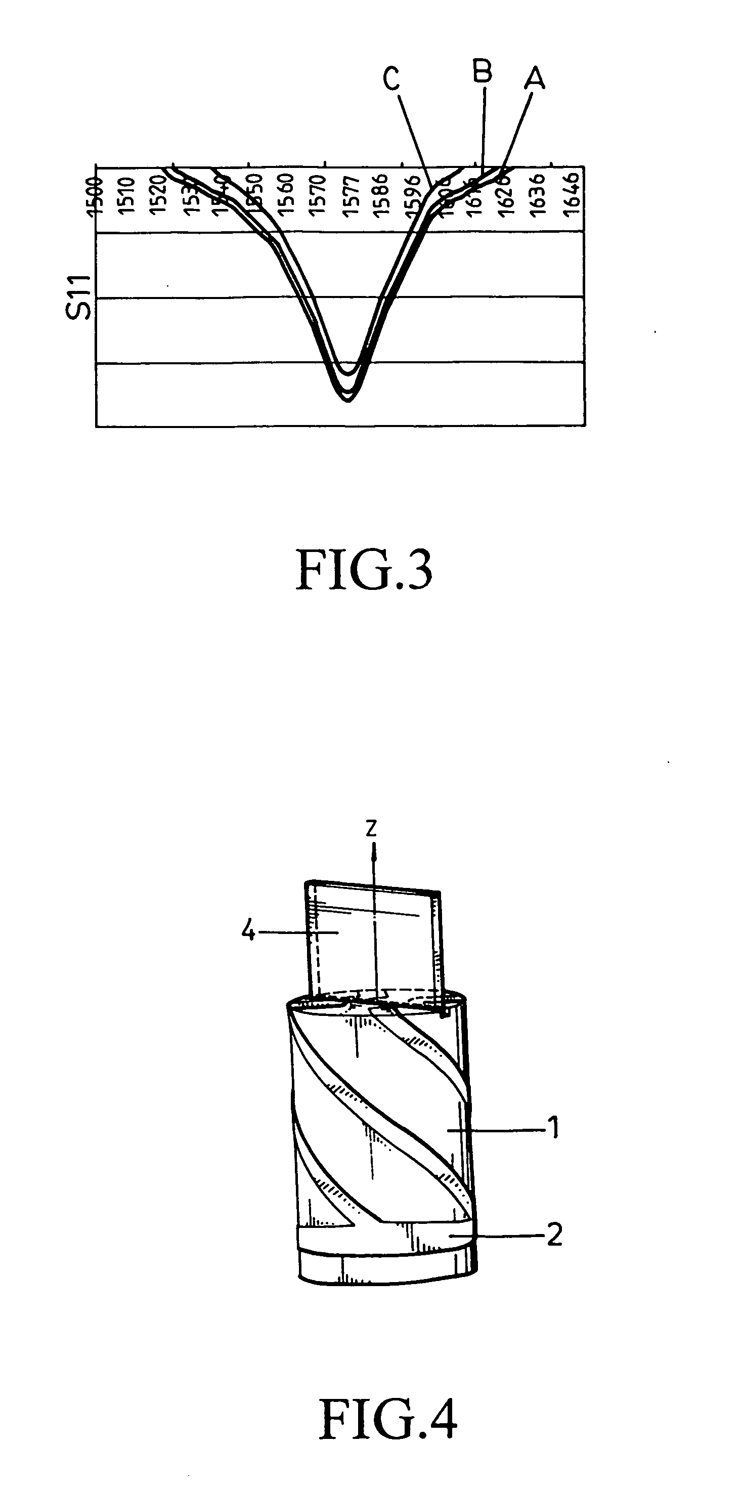
[0011] Referring to FIG. 1 and FIG. 2, the present invention comprises a cylindrical ceramic body 1, a metallic ring 2, and a ceramic ground plane 3 or PCB (Printed Circuit Board). The ceramic body 1 is made of microwave dielectric material with the dielectric constant equal to or greater than 20 to effectively reduce the length of radiation metallic electrodes. The metallic ring 2 is printed on the cylindrical surface of the ceramic body 1, and the height difference of the metallic ring 2 on the ceramic body 1 forms spiral radiation metallic electrodes 21, 22, 23, and 24 with various lengths, causing 90 degrees of phase difference between the neighboring spiral radiation metallic electrodes. The length of radiation metallic electrodes 21 and 24 is less than that of the other two radiation metallic electrodes 22, and 23, and its difference is equal to / 4 of operating frequency. With this design, two mutually perpendicular polarized electromagnetic fields are formed to create CPW (Ci...


PUM


Abstract

A spiral cylindrical ceramic circular polarized antenna, wherein a cylindrical ceramic body is made of microwave ceramic material with the dielectric constant equal to or greater than 20, and spiral radiation metallic electrodes are printed on the ceramic body to cause 90 degrees of phase difference between the neighboring spiral radiation metallic electrodes. A BALUN and transformer component, PCB, or ceramic ground plane is configured on the bottom tie-plate of the ceramic body to transfer the feed signal from unbalanced signal to balanced signal and to offer a matching impedance. With this design, two mutually perpendicular electromagnetic fields are formed to create CPW (Circular Polarized Wave), in order to facilitate the reception of GPS satellite signal.

Description

BACKGROUND OF THE INVENTION [0001] a) Field of the Invention The present invention relates to an antenna, and more particularly to a GPS (Global Positioning System) antenna that minimizes the volume of the antenna set and the influence of ambient environment to the radiation pattern of the antenna, and that is omni antenna such that signal can be received at any position when the antenna is integrated with PDA (Personal Digital Assistant), cellular phones, or GPS hand-held devices. [0002] b) Description of the Prior Art [0003] Most of the energy emitted and received by radio wave for conventional microwave antenna hand-held electronic devices or other communication products will be affected by hand, head, or body of a user, and the near-field energy is huge by the antenna, thereby wasting most of the radiation energy and causing the efficiency and response of the antenna to be worse than expected. Moreover, the conventional antenna must use metal for grounding, and its radiation pat...

Claims


Application Information

Patent Timeline
IPC IPC(8): H01Q1/36
CPCH01Q1/362H01Q11/08H01Q1/38
Inventor FENG, I-PENGKO, HSIN-HO
Owner FENG I PENG
Why Eureka
Try Eureka