
Light-emitting diode lamp

Inactive Publication Date: 2010-02-18
CHANG WAH ELECTROMATERIALS INC
View PDF10 Cites 60 Cited by
  • Summary
  • Abstract
  • Description
  • Claims
  • Application Information

AI Technical Summary

Benefits of technology

[0008]The invention provides a light-emitting diode (LED) lamp having favorable efficiency in heat dissipation.
[0024]To conclude, the LED lamp of the invention has the fan and the heat dissipation fins disposed therein. Consequently, the heat generated by the LED array module can be actively dissipated by the fan and passively dissipated by the heat dissipation fins. As a result, the heat dissipation efficiency of the LED lamp is improved. In other words, the LED lamp of the invention would not be easily damaged due to overheating.

Problems solved by technology

More specifically, electrons and holes in the semiconductor material will be combined to release excessive energy in the form of light when a current is applied to the semiconductor material.
Generally speaking, high-power LEDs all encounter heat dissipation problem.
When an LED is operated in an overly high temperature, the brightness of the LED lamp may be reduced and the lifespan of the LED may be shortened.

Method used


Image

  • Light-emitting diode lamp
  • Light-emitting diode lamp
  • Light-emitting diode lamp

Examples


Embodiment Construction

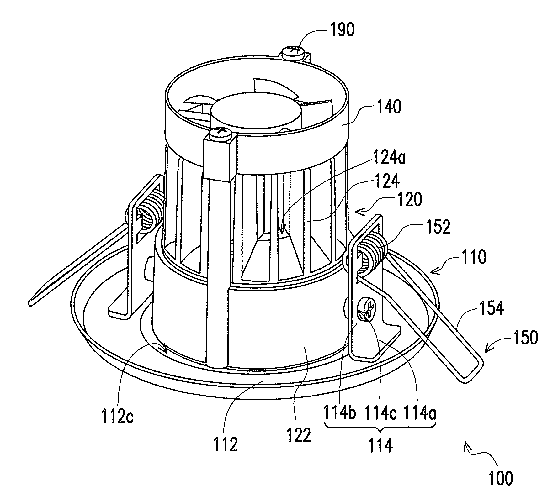
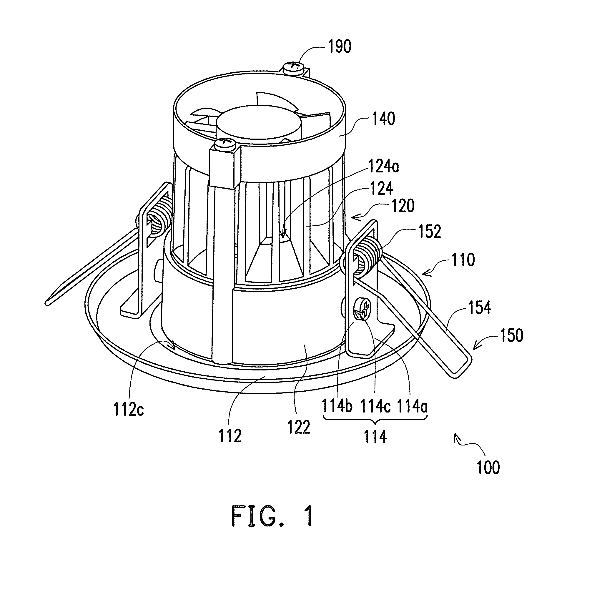
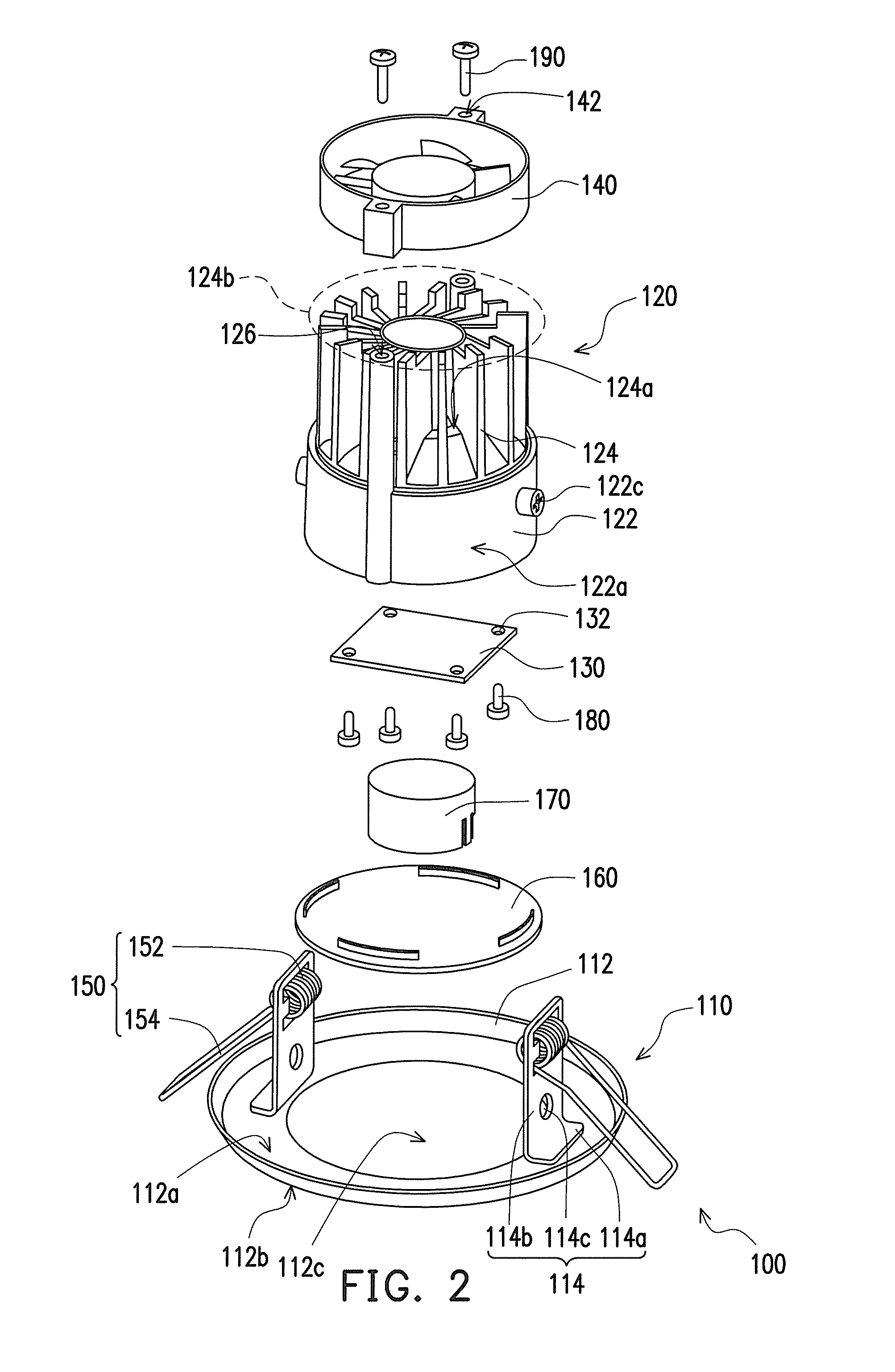
[0031]FIG. 1 is a schematic perspective view of an LED lamp according to one embodiment of the invention; FIG. 2 is a schematic exploded view of the LED lamp in FIG. 1; and FIG. 3 is a schematic perspective view depicting the LED lamp in FIG. 1 from another aspect. Referring to FIG. 1 and FIG. 2, in this embodiment, an LED lamp 100 is suitable for being electrically connected to a power supply (not shown). The LED lamp 100 includes a frame 110, a body 120, an LED array module 130, and a fan 140.

[0032]To be more specific, the frame 110 has a bottom plate 112 and a plurality of posts 114 connected with the bottom plate 112 (FIG. 1 and FIG. 2 illustrate two posts as an example). The bottom plate 112 has a top surface 112a, a bottom surface 112b opposite to the top surface 112a, and an opening 112c. Each of the posts 114 includes a base portion 114a, a rod portion 114b, and a first locking portion 114c. The base portions 114a are respectively fixed on the top surface 112a and located be...


PUM


Abstract

A light-emitting diode (LED) lamp suitable for being electrically connected with a power supply includes a frame, a body connected to the frame, and an LED array module and a fan disposed on the body. The frame includes a bottom plate having an opening and a plurality of posts each having a first locking portion. The body has a base and a plurality of heat dissipation fins. The base has an accommodating space corresponding to the opening and a plurality of second locking portions. The second locking portions are respectively locked with the first locking portions. An air channel is between any two adjacent heat dissipation fins. The LED array module located in the accommodating space and the fan are electrically connected with the power supply. The fan is for generating an airflow blowing the air channels and the base for dissipating heat from the LED array module.

Description

CROSS-REFERENCE TO RELATED APPLICATION[0001]This application claims the priority benefits of U.S. provisional application Ser. No. 61 / 088,016, filed on Aug. 12, 2008 and Taiwan patent application serial no. 98214554, filed on Aug. 6, 2009. The entirety of each of the above-mentioned patent applications is hereby incorporated by reference herein and made a part of specification.BACKGROUND OF THE INVENTION[0002]1. Field of Invention[0003]The invention relates to a light-emitting diode (LED) lamp and particularly to an LED lamp having favorable efficiency in heat dissipation.[0004]2. Description of Related Art[0005]A light-emitting diode (LED) is a semiconductor device that is fabricated basically by using a compound of chemical elements selected from groups III-V, such as GaP, GaAs, and so forth. This kind of semiconductor material has properties of converting electrical energy into light. More specifically, electrons and holes in the semiconductor material will be combined to release...

Claims


Application Information

Patent Timeline
IPC IPC(8): F21V29/00
CPCF21S8/026F21V21/02F21V29/773F21V29/02F21Y2101/02F21V21/046F21Y2115/10F21V19/0055F21V29/67
Inventor TSAI, WEN-KUEI
Owner CHANG WAH ELECTROMATERIALS INC
Features
  • Generate Ideas
  • Intellectual Property
  • Life Sciences
  • Materials
  • Tech Scout
  • Unparalleled Data Quality
  • Higher Quality Content
  • 60% Fewer Hallucinations
Learn More