Electric power steering device

a technology of electric power steering and power steering relay, which is applied in the direction of steering initiation, instruments, vessel construction, etc., can solve the problems of providing an expensive phase opening relay and saving costs, and achieve the effect of reducing vibration, maximizing the output ratio of the other one, and improving quiet operation

Active Publication Date: 2010-02-18
JTEKT CORP
View PDF7 Cites 20 Cited by
  • Summary
  • Abstract
  • Description
  • Claims
  • Application Information

AI Technical Summary

Benefits of technology

[0006]Accordingly, it is an objective of the present invention to provide an electric power steering device that responds to increased output and ensures improved steering feel.

Problems solved by technology

Also, the size of the non-permanent magnet motor does not easily cause a problem in a steering column, which occupies a relatively small installation space.
Accordingly, unlike a permanent magnet motor (such as a BLDC motor), which is often used in the electric power steering device, it is unnecessary to provide an expensive phase opening relay in order to prepare for malfunctions due to a phase-locked energization.
The phase opening relay is thus omitted, which saves the cost.

Method used


Image

  • Electric power steering device
  • Electric power steering device
  • Electric power steering device

Examples


first embodiment

[0032]A first embodiment of the present invention will now be described with reference to FIGS. 1 to 5.

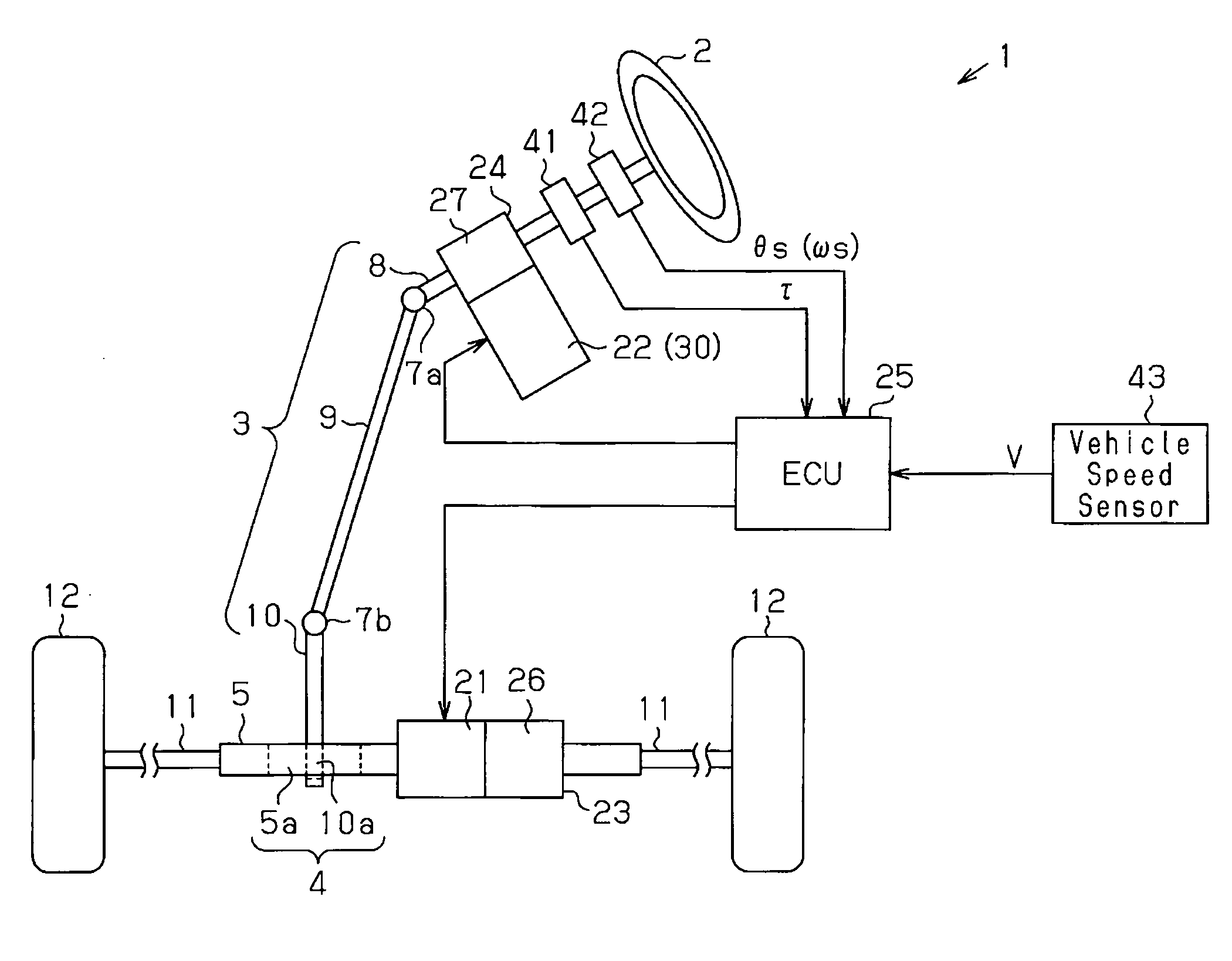
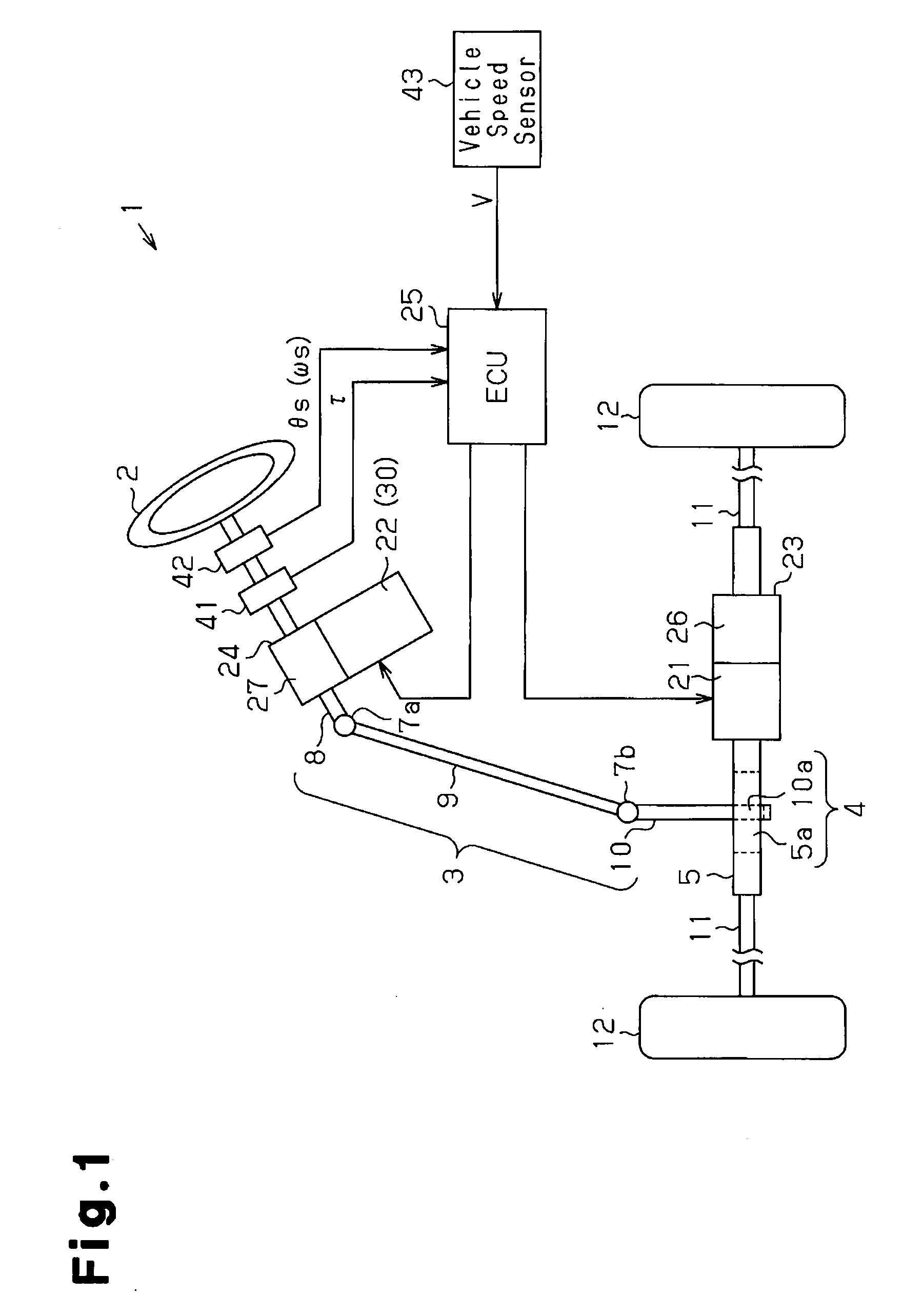
[0033]As shown in FIG. 1, in an electric power steering device (EPS) 1, a steering wheel 2 is fixed to a steering shaft 3. The steering shaft 3 is connected to a rack shaft 5 through a rack and pinion mechanism 4. Rotation of the steering shaft 3 caused through steering is converted into linear reciprocation of the rack shaft 5 through the rack and pinion mechanism 4. Specifically, a column shaft 8, an intermediate shaft 9, and a pinion shaft 10 are connected together through universal couplings 7a, 7b in the steering shaft 3. In the rack and pinion mechanism 4, pinion teeth 10a formed at one end of the pinion shaft 10 and rack teeth 5a provided in the rack shaft 5 are mutually engaged. A tie rod 11 is connected to each end of the rack shaft 5. The linear reciprocation of the rack shaft 5 is transmitted to a non-illustrated knuckle through the tie rods 11. This changes the steering...

second embodiment

[0062]A second embodiment of the present invention will hereafter be described with reference to FIGS. 6 to 9. Detailed description of components of the second embodiment that are the same as or like corresponding components of the first embodiment will be omitted.

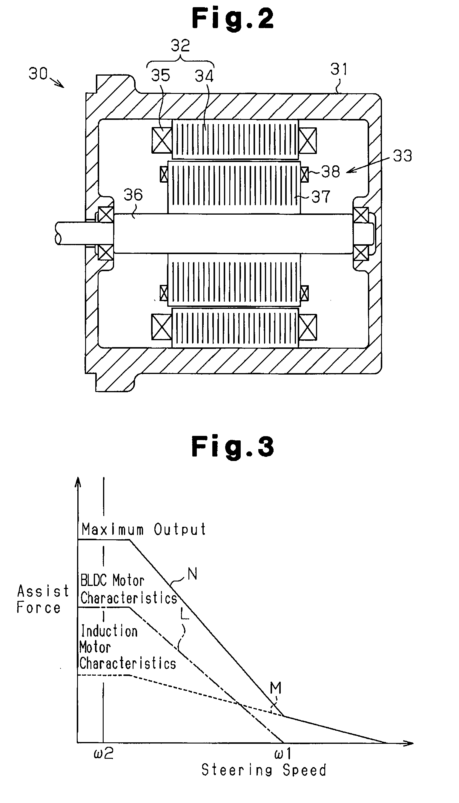
[0063]An EPS employing a motor as a drive source disadvantageously has a range of rotation in which noise specific to the motor easily occurs, or a range of the natural vibration. This problem of the range of the natural vibration cannot be solved by countermeasures involving control or configuration of the motor itself. Accordingly, in order to prevent the vibration generated by the motor from being transmitted to other components, the mounting portion of the motor, for example, has conventionally been constructed to prevent vibration. Considering this, in the EPS 1 of the present embodiment, if the steering speed (the rotation speed) of one of the motors 21, 22 corresponds to the range of the natural vibration and the re...


PUM


Abstract

An electric power steering (EPS) device including a rack actuator that applies assist force to a rack shaft, a column actuator that applies assist force to a column shaft, and an ECU that controls operation of the actuators by supplying drive power to motors, each of which is a drive source of the corresponding one of the actuators. A permanent magnet motor (BLDC) is employed as the motor of the rack actuator and an induction motor, which is a non-permanent magnet motor, is used as the motor of the column actuator.

Description

TECHNICAL FIELD[0001]The present invention relates to an electric power steering device having a plurality of motors.BACKGROUND ART[0002]Conventionally, an electric power steering device (EPS) having a motor as a drive source is known as a power steering device for a vehicle. Compared to hydraulic power steering devices, the EPS characteristically enables flexible layout and reduces energy consumption. Accordingly, use of the EPS is now considered in not only small-sized vehicles but also large-sized vehicles. As a result, corresponding improvement is strongly demanded in the output performance of the EPS.[0003]However, there is actually only a limited space for installing an EPS actuator in a vehicle. Particularly, if the EPS is a rack type or a pinion type, it is practically impossible to accommodate a large-sized motor. Further, in the case of a column type EPS, which occupies a relatively small space, the weight of the device is disadvantageously increased by reinforcing a steer...

Claims


Application Information

Patent Timeline
Patent Type & Authority Applications(United States)
IPC IPC(8): B62D5/04G06F19/00
CPCB62D5/008B62D5/046B62D5/04
Inventor SHIBATA, YOSHIYUKINAKANO, JIRO
Owner JTEKT CORP
Why Eureka
Try Eureka