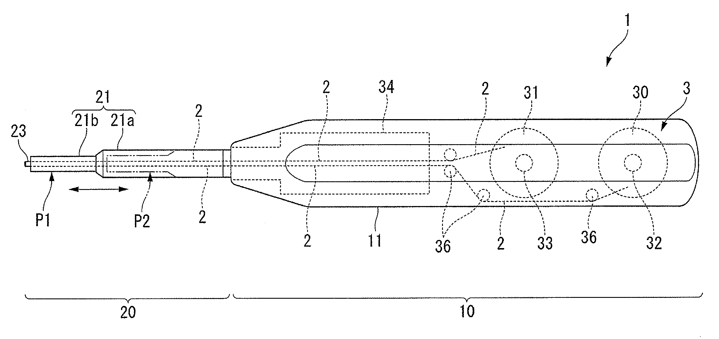
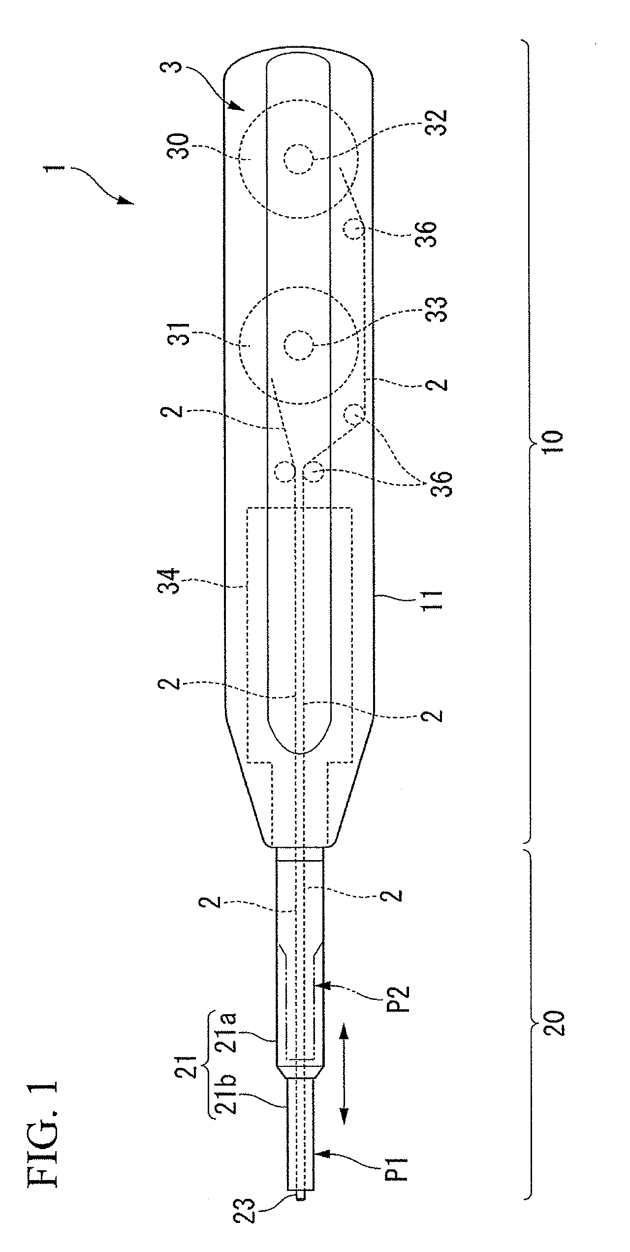
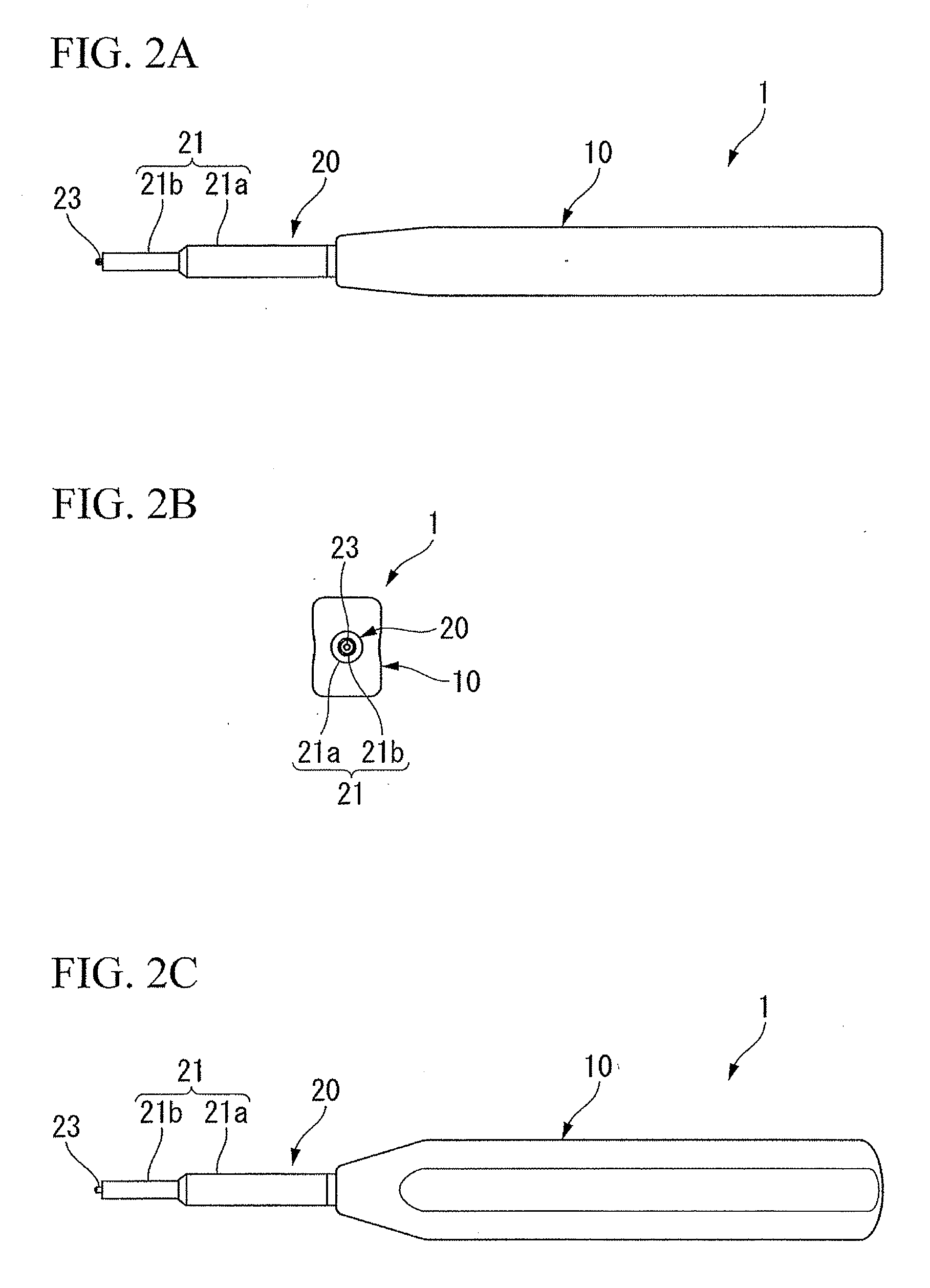
Optical connector cleaning tool
a cleaning tool and optical connector technology, applied in the direction of carpet cleaners, instruments, photosensitive materials, etc., can solve the problems of increased transmission loss, damage during connection and disconnection, etc., and achieve the effect of reducing the size of the tool body, facilitating operation, and simplifying the configuration of the mechanism that rotates the head member
- Summary
- Abstract
- Description
- Claims
- Application Information
AI Technical Summary
Benefits of technology
Problems solved by technology
Method used
Image
Examples
second embodiment
[0200]FIG. 10 to FIG. 26D show the cleaning tool of the present invention.
[0201]FIG. 10 is a perspective view of a cleaning tool 1A of this embodiment. FIG. 11A and FIG. 11B are respectively an elevation view and a side view of the cleaning tool 1A. FIG. 12 is an exploded perspective view of the cleaning tool 1A. FIG. 13A to FIG. 13C show a supporting member 51 of a rotary mechanism 5, and are respectively an elevation view, side view, and back view thereof. FIG. 14 is a perspective view of the supporting member 51. FIG. 15 is a perspective view which shows a rotary shaft 52 of the rotary mechanism 5. FIG. 16 is an enlarged perspective view of the essential elements of the rotary shaft 52. FIG. 17 is a perspective view of the head member 23. FIG. 18A and FIG. 18B are a front view and elevation view of the head member 23. FIG. 19 is a partial cross-sectional view which shows the rotary shaft 52 and the head member 23 attached to its distal end. FIG. 20 is an elevation view which show...
third embodiment
[0280]The structure of a cleaning tool 101 which is the cleaning tool of the present invention is described below.
[0281]FIG. 32 is a perspective view of the cleaning tool 101. FIG. 33 is an enlarged perspective view of the essential elements of the cleaning tool 101. FIG. 34A to FIG. 34D are respectively a front view, back view, side view, and elevation view of the cleaning tool 101. FIG. 35 is an exploded perspective view of the cleaning tool 101. FIG. 36A to FIG. 36C show a supporting member 151, and are respectively an elevation view, side view, and back view. FIG. 37 is a perspective view of the supporting member 151. FIG. 38 is a perspective view which shows a rotary shaft 152 of a rotary mechanism 105. FIG. 39 is an enlarged perspective view of the essential elements of the rotary shaft 152. FIG. 40 is a perspective view of a head member 123, viewed from one side. FIG. 41 is a perspective view of the head member 123, viewed from the other side. FIG. 42 is an elevation view of ...
fourth embodiment
[0391]The structure of a cleaning tool 201 which is the cleaning tool of the present invention is described below.
[0392]FIG. 71A to FIG. 71D are respectively a front view, back view, side view, and elevation view of the cleaning tool 201. FIG. 72 is an exploded perspective view of the cleaning tool 201. FIG. 73 is an elevation view which shows a connector cleaning attachment 240. FIG. 74 is a cross-sectional view which shows the connector cleaning attachment 240. FIG. 75 is a front view of the connector cleaning attachment 240. FIG. 76 is a rear view of the connector cleaning attachment 240. FIG. 77 is a perspective view of the connector cleaning attachment 240. FIG. 78 is a perspective view of the connector cleaning attachment 240 in cross-section. FIG. 79 is a cross-sectional view of the connector cleaning attachment 240, and is a drawing which shows the track of a notch 253 during opening and closing operation of a covering part 242. FIG. 80 is a cross-sectional view which shows ...
PUM
 Abstract
Description
Claims
Application Information
 - R&D
- Intellectual Property
- Life Sciences
- Materials
- Tech Scout
- Unparalleled Data Quality
- Higher Quality Content
- 60% Fewer Hallucinations
Browse by: Latest US Patents, China's latest patents, Technical Efficacy Thesaurus, Application Domain, Technology Topic, Popular Technical Reports.
© 2025 PatSnap. All rights reserved.Legal|Privacy policy|Modern Slavery Act Transparency Statement|Sitemap|About US| Contact US: help@patsnap.com


