Tuning device

Inactive Publication Date: 2010-02-25
SEIKO INSTR INC
View PDF1 Cites 13 Cited by
  • Summary
  • Abstract
  • Description
  • Claims
  • Application Information

AI Technical Summary

Benefits of technology

[0008]Therefore, the present invention has been made in view of the above-mentioned circumstances, and an object thereof is to provide a tuning device capable of improving durability thereof without impairing a tuning function.

Problems solved by technology

However, placing the tuning device in the above-mentioned position raises a problem in that the bell conceals a display surface from view.
Incidentally, in the tuning device disclosed in JP 2003-255932 A, wirings are used to connect the vibration sensor attached to the clip portion and the circuit board disposed inside the display portion with each other, and when the display portion is caused to pivot, the wirings arranged inside the joint are caused to pivot together, which may result in the twisted wirings.
This leads to a problem that the wirings are broken in a short period of time.
However, such a structure makes it difficult for the vibration sensor to sense the sound, leading to a problem that performance as the tuning device may be lowered.

Method used


Image

  • Tuning device
  • Tuning device
  • Tuning device

Examples


first embodiment

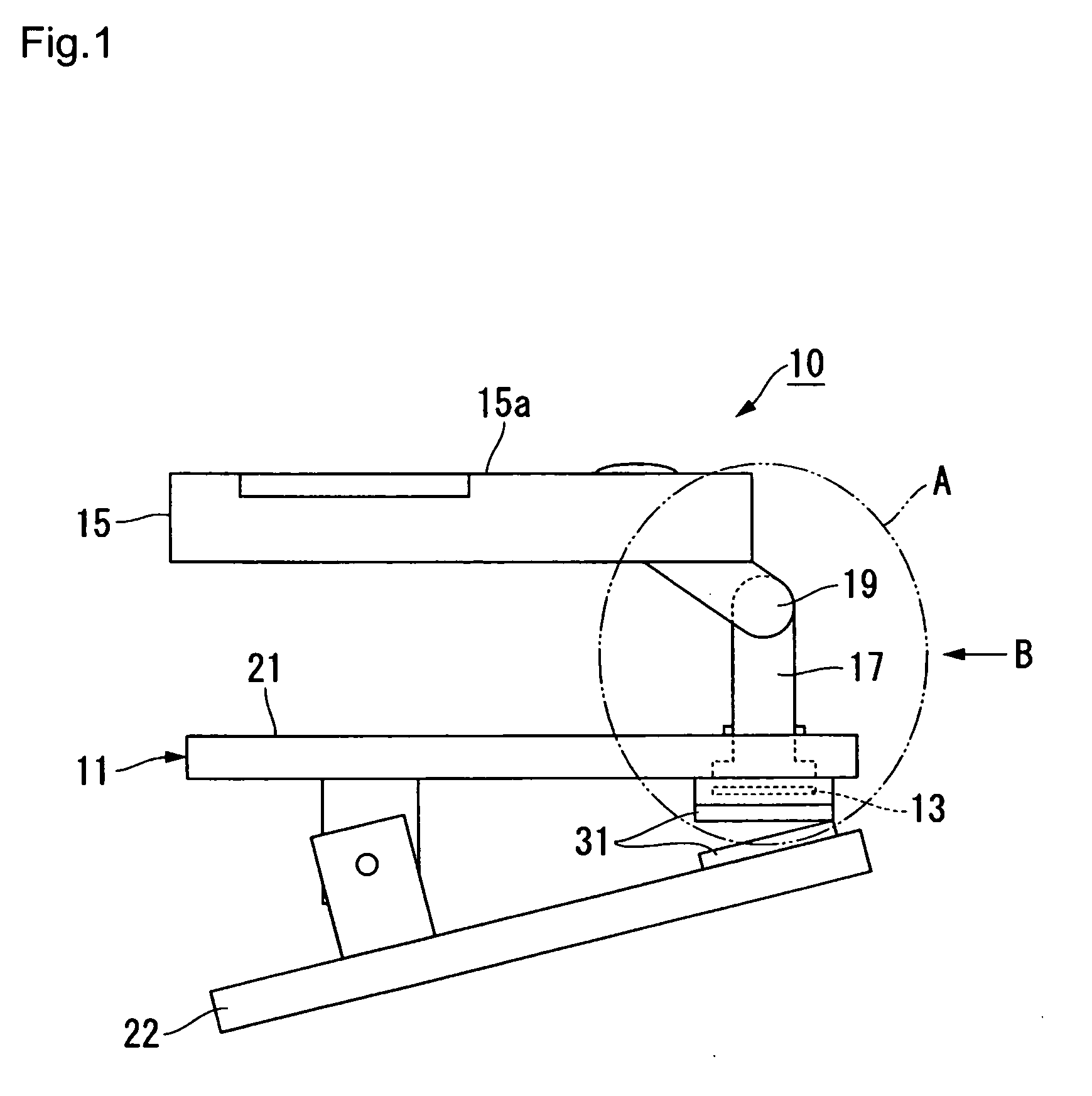
[0038]Next, description is made of a tuning device according to a first embodiment of the present invention based on FIGS. 1 to 6.

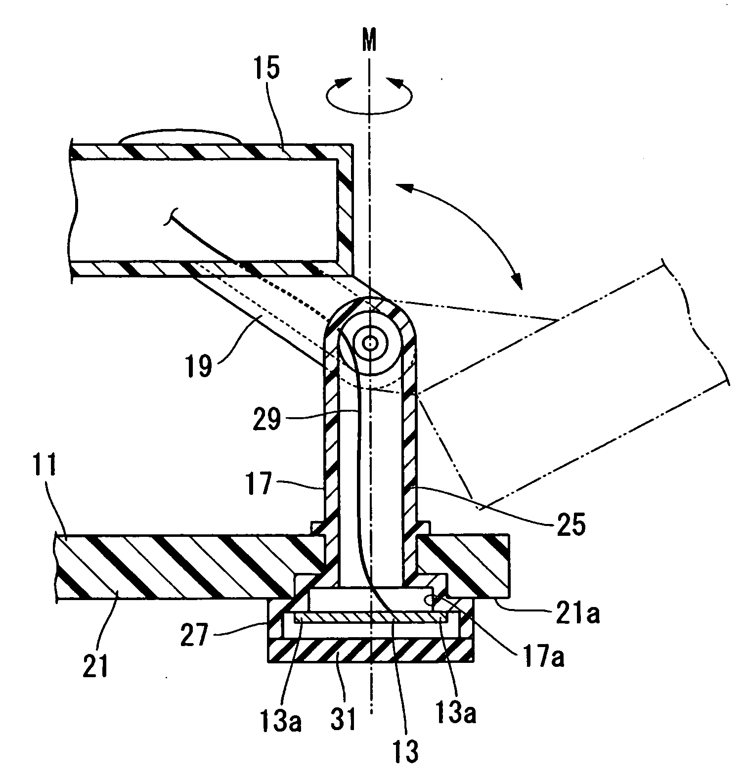
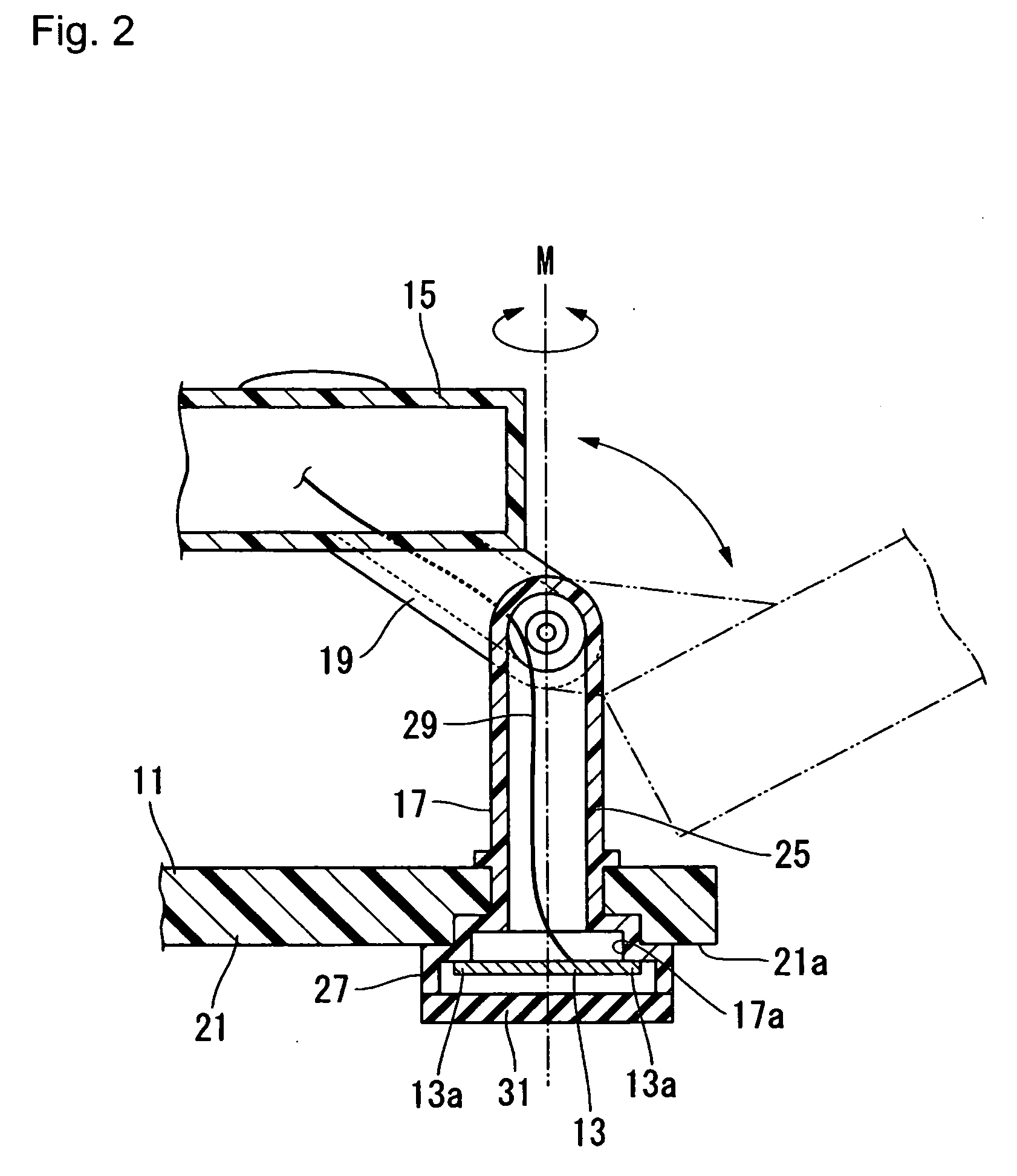
[0039]As illustrated in FIG. 1, a tuning device 10 includes: a clip portion 11 including a pair of plate materials 21 and 22 adapted to be engaged with each other; a vibration sensor 13 for detecting a vibration state of a sound emitted from a musical instrument; a display portion 15 that is mounted with an electronic circuit (not shown) for processing an electrical signal transmitted from the vibration sensor 13 and a battery (not shown) for driving the electronic circuit and is configured to be able to display a judgment result thereof; and a first pivot portion 17 and a second pivot portion 19 that join the clip portion 11 and the display portion 15 to each other.

[0040]The clip portion 11 may pinch the vicinity of a sound emitting portion of the musical instrument with the pair of plate materials 21 and 22 by a repulsive force of a spring material disp...

second embodiment

[0060]Next, description is made of a tuning device according to a second embodiment of the present invention based on FIGS. 7 to 10. Note that this embodiment is different from the first embodiment only in the structures of the first pivot portion and the second pivot portion, while the other components and portions are substantially the same as those of the first embodiment, and hence the same components and portions are denoted by the same reference symbols to thereby omit detailed description thereof.

[0061]As illustrated in FIG. 7, a first pivot portion 117 of a tuning device 110 is a member made of, for example, resin and having a substantially cylindrical shape. The first pivot portion 117 includes: the shaft portion 25 structured to be rotatable about the axis M by 360 degrees; and the containing portion 27 formed in the end portion on the plate material 21 side of the shaft portion 25 so as to have a larger diameter. The containing portion 27 contains the vibration sensor 13 ...


PUM


Abstract

Provided is a tuning device including: a tuning device main body including an electric circuit for computing a tuning state of a musical instrument; a clip portion including a pair of plate materials for attaching the tuning device main body to the musical instrument; a joint member for joining the tuning device main body and the clip portion; and a vibration sensor for sensing a sound emitted from the musical instrument, the joint member including: a first pivot portion for making the clip portion free to pivot about an extension direction of the joint member; and a second pivot portion for making the tuning device main body free to pivot about a direction perpendicular to the extension direction. The vibration sensor is incorporated into the joint member, and is structured to be rotatable about the extension direction unitarily along with the tuning device main body.

Description

BACKGROUND OF THE INVENTION[0001]1. Field of the Invention[0002]The present invention relates to a tuning device.[0003]2. Description of the Related Art[0004]Up to now, there are known tuning devices configured to perform tuning by using pitch information of an arbitrary input sound as a reference. FIG. 11 illustrates a structure of a conventional tuning device 400. A microphone 401 and a vibration sensor 405 each sample a sound emitted from a musical instrument, and convert the sound into an electrical signal. An amplifier 402 receives an output signal from at least one of the microphone 401 and the vibration sensor 405, and amplifies the electrical signal to a desired level. A CPU 403 includes pitch extracting means for receiving an output signal from the amplifier 402 and extracting from the output signal a fundamental period of the sound sampled by at least one of the microphone 401 and the vibration sensor 405. In addition, the CPU 403 includes reference sound setting means, by...

Claims


Application Information

Patent Timeline
IPC IPC(8): G10G7/02
CPCG10G7/02G10D9/00
Inventor NAGAKURA, FUMIYOSHI
Owner SEIKO INSTR INC
Why Eureka
Try Eureka