
Device for the welding of plastic membranes

Inactive Publication Date: 2010-02-25
SIKA TECH AG
View PDF5 Cites 1 Cited by
  • Summary
  • Abstract
  • Description
  • Claims
  • Application Information

AI Technical Summary

Benefits of technology

[0009]The advantages of the invention are to be seen, inter alia, in that the devices according to the invention for the welding of plastic membranes, with a movable holding of the nozzle attachment, ensure that the pressure force of the nozzle attachment is always sufficiently high. By the nozzle attachment being held movably, and because of the constant

Problems solved by technology

This change in nature makes it difficult to weld the films satisfactorily and may necessitate complicated preparatory work, in particular cleaning op

Method used


Image

  • Device for the welding of plastic membranes
  • Device for the welding of plastic membranes
  • Device for the welding of plastic membranes

Examples


Example

[0021]Only the elements essential for an immediate understanding of the invention are shown. What are not illustrated, for example, are the hot-gas generator and the welding machine, such as are known, for example, from EP 1 358 993.

WAY OF IMPLEMENTING THE INVENTION

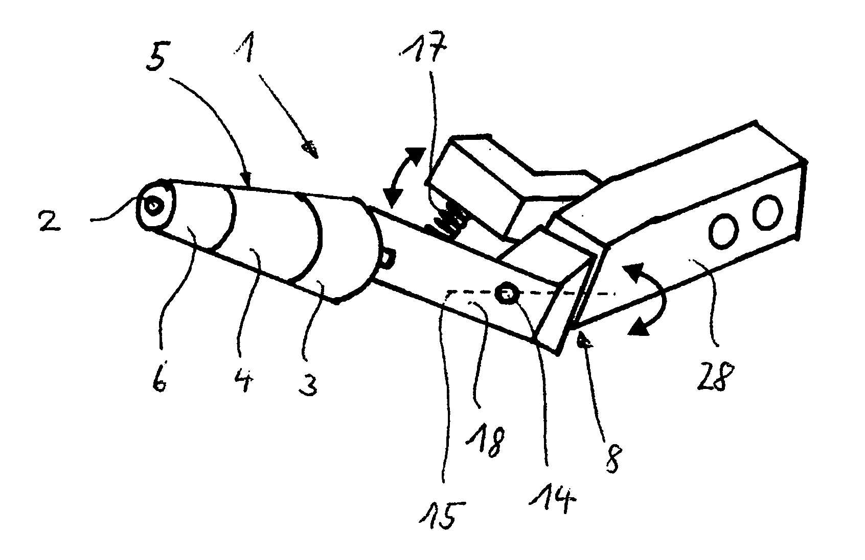
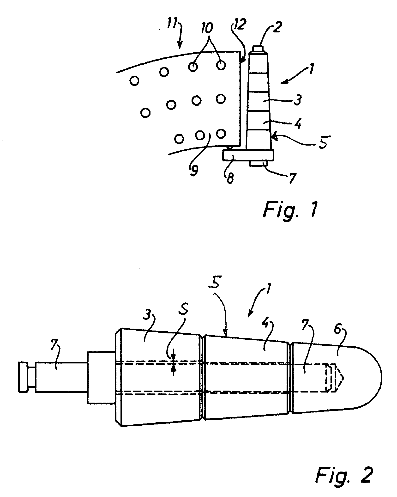
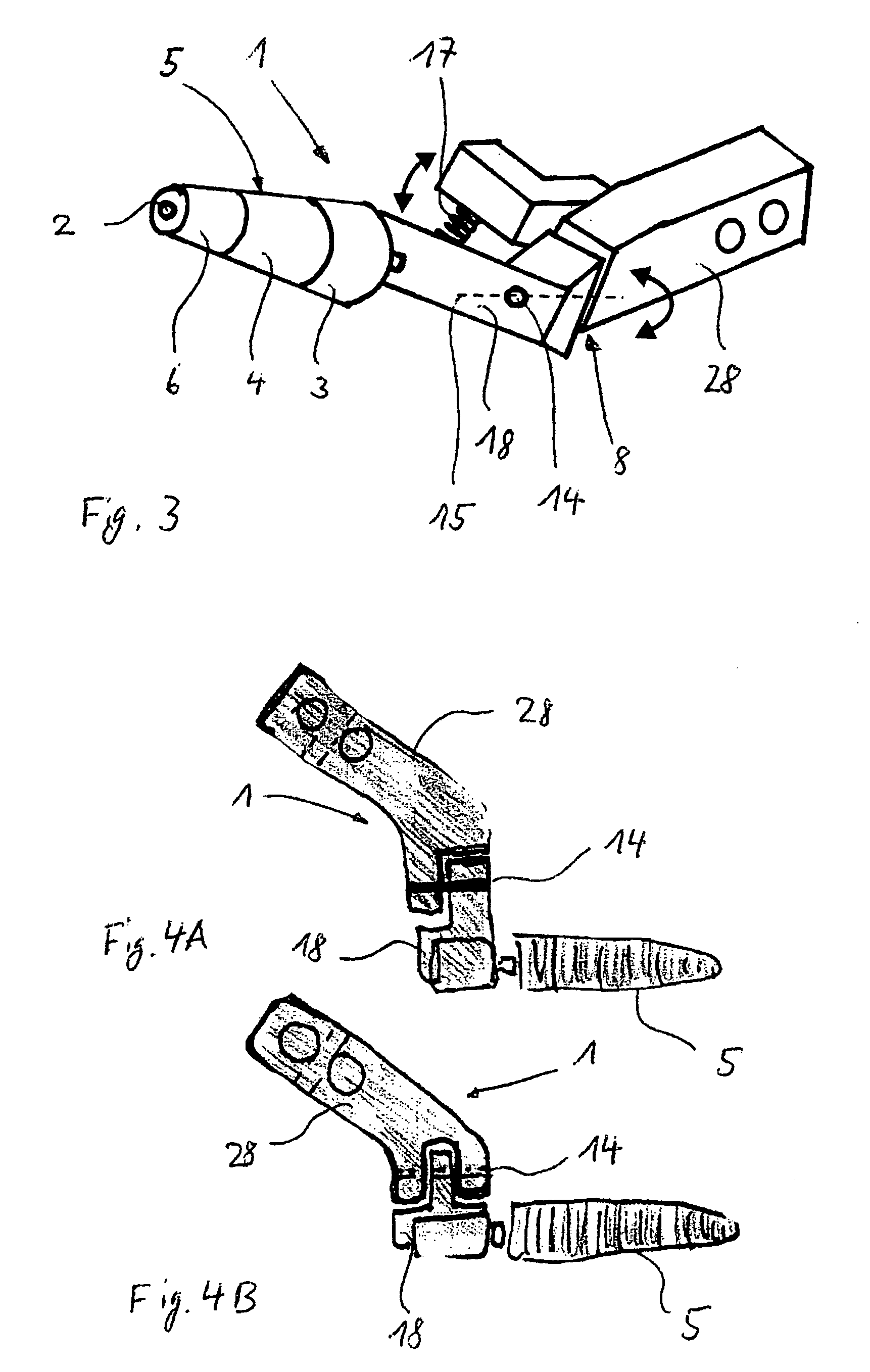
[0022]The device, illustrated in FIG. 1, for the welding of plastic membranes comprises a hot-air nozzle 11 and a nozzle attachment 1. The hot-air nozzle 11 has a slit-like outlet orifice 12 from which the hot air can emerge. Perforations or very small holes 10 are provided in the region of this outlet orifice 12 of the nozzle body 9. The hot air emerging from these perforations leads to a first softening of the film membranes arranged one above the other. This outlet orifice 12 is followed by the nozzle attachment 1 which comprises a rubbing arrangement, a rubbing member 5. The rubbing member 5 may be formed from a plurality of rubbing member elements, rubbing cylinders 3, 4, arranged next to one another. The rubbing mem...


PUM

PropertyMeasurementUnit
Fractionaaaaaaaaaa
Forceaaaaaaaaaa
Sizeaaaaaaaaaa

Abstract

The invention relates to a device for the heat sealing of plastic membranes that contain a nozzle attachment, with the nozzle attachment having an abrasive member and being held flexibly. Thus, the nozzle attachment is positioned with a defined force on the lower membrane that is to be heat sealed, resulting in a seam of consistently high quality.

Description

TECHNICAL FIELD[0001]The present invention relates to a device for the welding of films or plastic membranes according to the preamble of claim 1.PRIOR ART[0002]Devices for the welding of plastic membranes are used particularly for connecting plastic membranes in order to seal off buildings or civil engineering structures, in particular in earthworks and hydraulic engineering structures, for example in the case of flat roofs, pitched roofs, tent-like roof structures, swimming pools, etc., and, in particular, must conform to the Directives of the German Association for Welding Technology “DVS 2225”.[0003]For the hot-gas welding of plastic membranes of this type, devices are used, such as are known, for example, from WO 2004 / 085759 or U.S. Pat. No. 6,325,126. These devices have a hot-gas blower, by means of which heated air at a temperature of approximately 250° to 600° Celsius is blown through a wide slit nozzle between the thermoplastic films in order to soften the film regions to b...

Claims


Application Information

Patent Timeline
IPC IPC(8): B32B37/00
CPCB29C65/10B29C66/02245B29C66/7373B29C66/80B29K2101/12B29K2021/00B29K2023/00B29K2027/06B29C66/8167B29C66/1122B29C66/43B29C66/71B29C66/73921B29K2021/003
Inventor VONEY, HANSRUEDIFLUCK, ARMIN
Owner SIKA TECH AG
Learn More