Rail vehicle having an attached deformation zone

a deformation zone and rail vehicle technology, applied in the direction of buffer cars, railway bodies, axle-box lubrication, etc., can solve the problems of unsatisfactory resolution of passengers' stress in the event of a crash, inability to reduce the acceleration of inability to achieve the reduction of acceleration. acted on the people located in the driver's cab, etc., to achieve good deformation behavior and high axial pressure forces

Active Publication Date: 2016-08-23
SIEMENS MOBILITY AUSTRIA GMBH
View PDF14 Cites 0 Cited by
  • Summary
  • Abstract
  • Description
  • Claims
  • Application Information

AI Technical Summary

Benefits of technology

[0009]The underlying object of the invention is therefore to specify a rail vehicle with attached deformation zone, which on the one hand can withstand very high axial pressure forces, on the other hand exhibits a good deformation behavior during accidents especially also with geometrically incompatible opposing parties and is especially designed for embodying vertical wagon ends.
[0013]A further development of the invention makes provision for arranging at least one deformation element in the deformation zone so that it does not participate in the transmission of operational loads but becomes effective during a collision after the collapse or failure of the force transmission element and dissipates the kinetic energy of the collision at least partly.
[0014]This enables the advantage to be obtained of being able to realize a rail vehicle which is able to safely resist specific longitudinal forces (coupling pressure, buffer pressure, end transverse beam pressure) but on the other hand has an energy-dissipating deformation behavior which minimizes the forces acting on the passengers during a collision.
[0019]An embodiment of the force transmission element makes provision for the individual plates which form the essentially X-shaped force transmission element to be embodied with different thicknesses in each case. This enables the advantage to be achieved of being able to precisely set the failure load and the direction of the buckling of the plates. Such an arrangement can be well designed with computer-aided simulation in relation to its strength (failure load) and also its plastic deformation behavior.
[0020]It is further recommended that one plate of this X-shaped arrangement is designed in one piece and with a greater thickness than the two other plates. This enables the failure load to be set more precisely.
[0021]It is further advantageous to assemble this X-shaped arrangement of plates from a number of plates, especially from three plates. In such a way the failure load and the buckling behavior can be set especially precisely.

Problems solved by technology

A combination of the demands for a high static coupling or transverse end beam pressure and for a crash behavior, which can reduce the maximum deceleration of the vehicle and thus the stress on the passengers in the event of a crash has not yet satisfactorily been resolved for the structurally integrated deformation zones.
A further complication in the resolution of this contradictory demand lies in the demand for right-angled wagon ends at the start and end of the train as well, which is especially preferably required in the USA.
In such cases the drivers are exposed to particular dangers since construction space for crash elements is only available to a restricted extent.
A reduction in the acceleration which acts on the people located in the driver's cab can however not be achieved by this solution.
A further difficulty for a construction optimized as regards deformation lies in the mixed-mode operation of passenger and freight traffic even on local transit routes in the USA, so that a plurality of vehicles come into consideration as opposing parties in a collision.
This is made more difficult in such cases by freight wagons and especially the locomotives widely used in the USA having practically no energy-dissipating properties.
These locomotives must be seen through their massive construction as rigid in practice and also are very likely, because of their greater height, to represent completely incompatible opposing parties for wagons in a collision.
Opposing collision parties which strike points not designed for a collision are to be seen as geometrically incompatible.
This is only very unsatisfactorily possible with the solutions according to the prior art.

Method used


Image

  • Rail vehicle having an attached deformation zone
  • Rail vehicle having an attached deformation zone
  • Rail vehicle having an attached deformation zone

Examples


Embodiment Construction

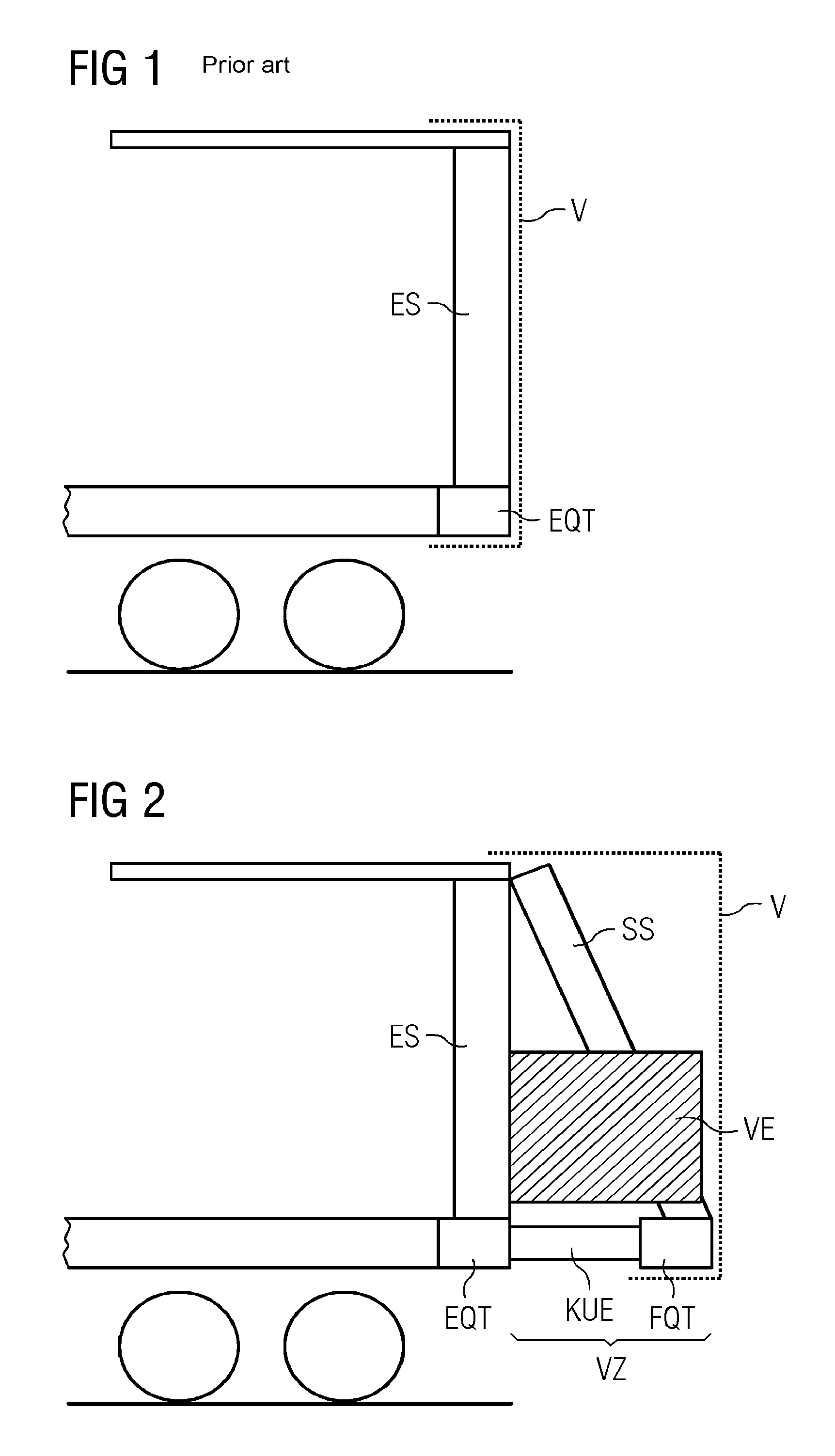
[0046]FIG. 1 shows an example in a schematic diagram of a rail vehicle with vertical wagon ends in accordance with the prior art in a side view. A vehicle end of a rail vehicle is shown having an end transverse beam EQT at its end.

[0047]Longitudinal forces act on this end transverse beam EQT, this end transverse beam EQT is correspondingly dimensioned for this purpose with attachment means for excepting buffers, couplings, etc.

[0048]Corner pillars ES are provided perpendicular to this end transverse beam EQT, which extend from the end transverse beam EQT to the roof of the rail vehicle.

[0049]The paneling V essentially serves the usual protection and design purposes and does not have any strength relevant during a collision. A rail vehicle in accordance with FIG. 1 has no significant energy-dissipating properties, in a collision high forces act on the passengers.

[0050]FIG. 2 shows an example in a schematic diagram of a rail vehicle with attached deformation zone in a side view. In pr...


PUM


Abstract

A rail vehicle having an attached deformation zone is presented. The rail vehicle has at least one end transverse beam provided in an end face region and corner pillars arranged substantially vertically and extend from the end transverse beam. The deformation zone is provided at the end face having a front transverse beam arranged parallel to the end transverse beam and spaced therefrom in an end-face direction and at least one force transmission element arranged between the end transverse beam and the front transverse beam. The element transmits longitudinal compressive forces between the end transverse beam and the front transverse beam without plastic deformation up to a defined value and failing when the defined value is exceeded.

Description

CROSS REFERENCE TO RELATED APPLICATIONS[0001]This application is the US National Stage of International Application No. PCT / EP2012 / 055310 filed Mar. 26, 2012 and claims benefit thereof, the entire content of which is hereby incorporated herein by reference. The International Application claims priority to the Austria application No. A476 / 2011 filed Apr. 4, 2011, the entire contents of which is hereby incorporated herein by reference.TECHNICAL FIELD[0002]The invention relates to a rail vehicle having an attached deformation zone.PRIOR ART[0003]Approval standards for rail vehicles include requirements for evidence of specific strength values of the wagon body. These standards require evidence for example that the rail vehicle can withstand a certain longitudinal force (coupling pressure, buffer pressure, pressure on end transverse beam) without sustaining damage. The UIC-566 standard applicable for Europe requires for example a verifiable coupling pressure of 2000 kN, the standard app...

Claims


Application Information

Patent Timeline
Patent Type & Authority Patents(United States)
IPC IPC(8): B61D15/06B61D17/06
CPCB61D15/06B61D17/06
Inventor GRAF, RICHARDHEINZL, PHILIPPSEITZBERGER, MARKUS
Owner SIEMENS MOBILITY AUSTRIA GMBH
Why Eureka
Try Eureka