[0016]The object on which the invention is based is, therefore, to provide a pneumatic spring pot of the type initially mentioned and a method for producing it, which is suitable for
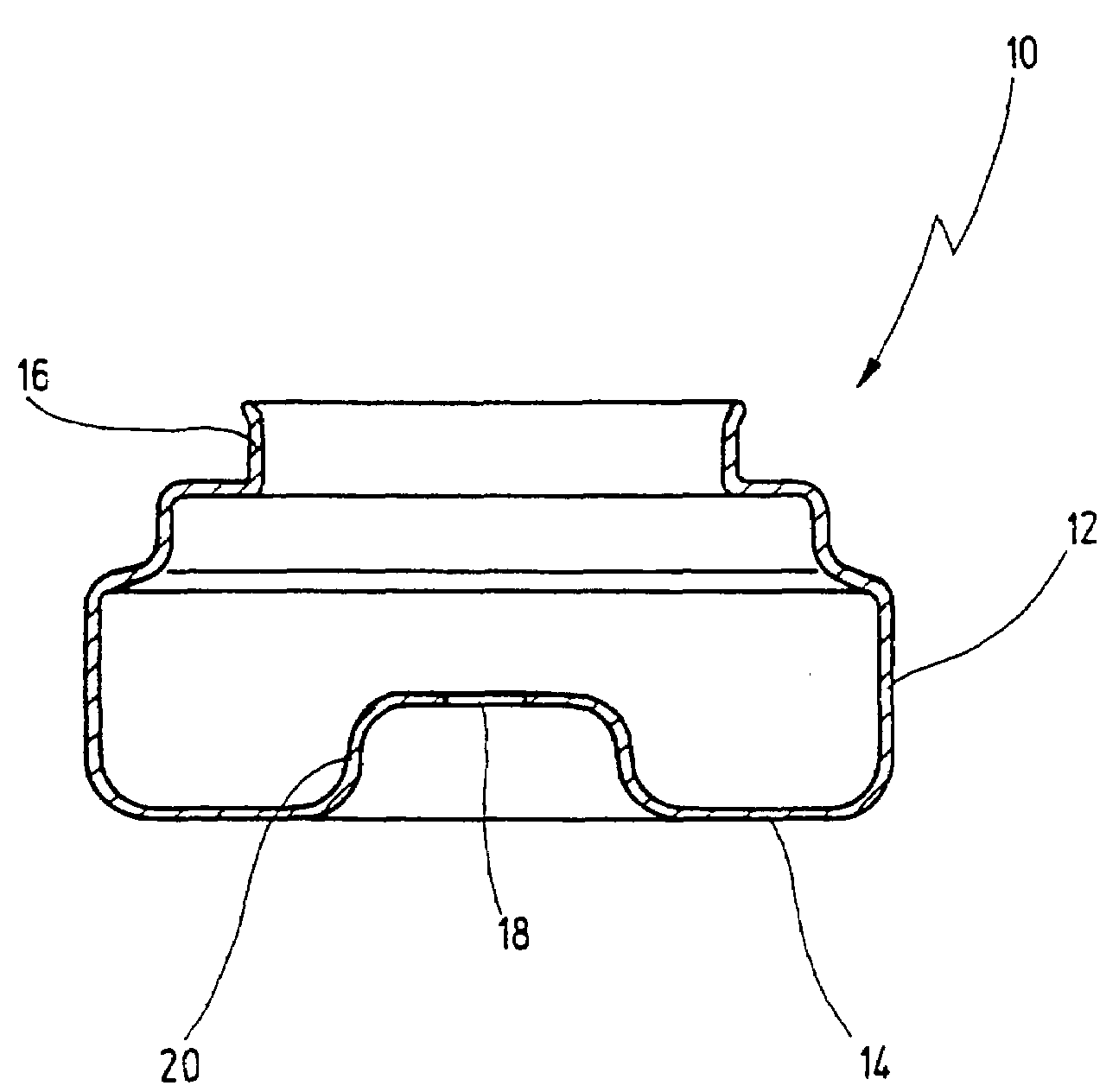
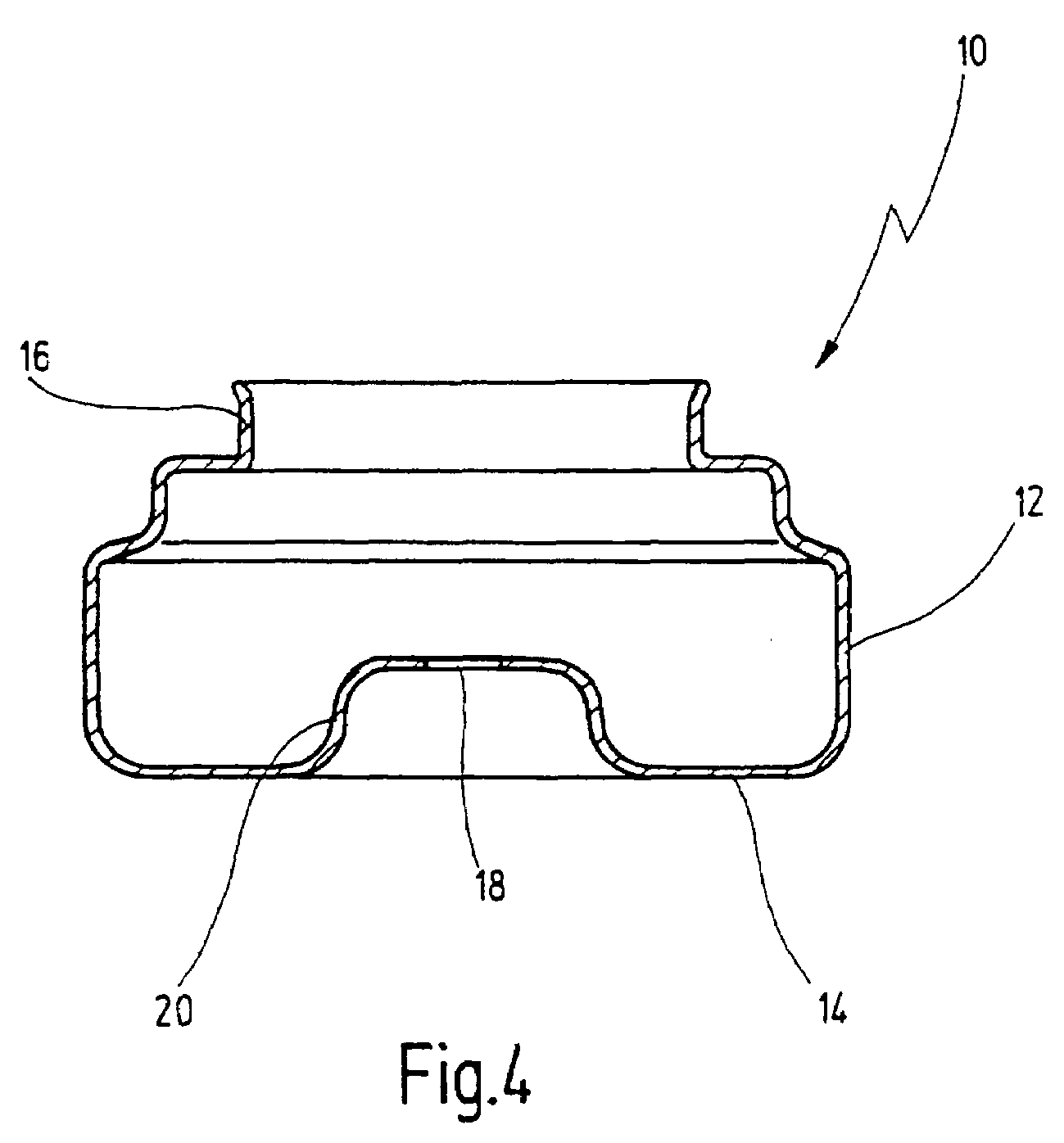
large series manufacture, and in which, in particular, the outlay in terms of material and cost is kept low, while at the same time the pneumatic spring pot has a high degree of functionality, and, in addition to the function of the fastening of the pneumatic concertina, the one-piece pneumatic spring pot is also to fulfil the function of receiving the
damper bearing.
[0020]The material consolidation in the region of the annular flange, brought about in the pneumatic spring pot according to the invention, has, then, the considerable
advantage that the supporting ring, which was necessary in the pneumatic spring pots for fastening the pneumatic spring concertina, can now be dispensed with in the pneumatic spring pot according to the invention, with the result that the cost outlay of the pneumatic spring pot is reduced even further. The pneumatic spring pot according to the invention has the further
advantage that, because the pneumatic spring pot is manufactured in one piece by sheet
metal forming from a single sheet bar, the number of operations is now reduced, in particular that the operation of
assembly, for example
welding or crimping, and of
leak testing becomes superfluous. Since the
welding operation is dispensed with, however, the pneumatic pot according to the invention achieves the further
advantage that the pneumatic spring pot can be formed from a surface-treated sheet bar, and the finished pneumatic spring pot subsequently no longer requires any further surface treatment for
corrosion protection, since the surface treatment or surface
tempering is not damaged by the sheet
metal forming, as is the case when the pneumatic spring pot is welded from two parts in the region of the
weld seam. The pneumatic spring pot according to the invention and the method according to the invention are distinguished by a low outlay in terms of material, at the same time with an increased functionality of the pneumatic spring pot with regard to its stability, since the abovementioned material consolidation occurs without the use of additional material, and by the correspondingly reduced outlay in terms of cost and also time, so that the pneumatic spring pot according to the invention and the method according to the invention are especially suitable for
large series manufacture.
[0024]
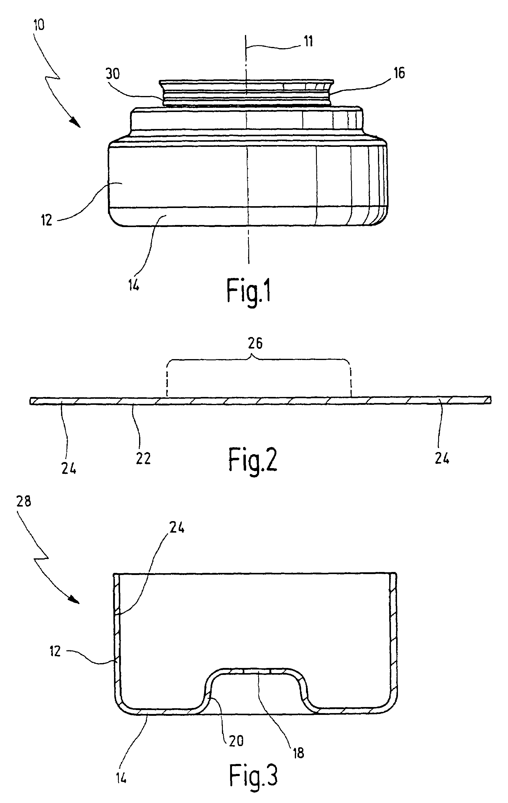
Deep drawing as sheet
metal forming has the advantage that a deep-drawing method is especially suitable for large series manufacture. The further advantage of
deep drawing is that the effect of material consolidation in the way mentioned above is particularly pronounced in the case of this sheet
metal forming method. The bottom and the pot wall can thus be drawn in a particularly cost-effective and time-saving way into a prepot, on which the annular flange is then formed later.
[0029]In the case of such a narrowing in diameter of the annular flange in relation to the largest diameter of the pot wall, a particularly pronounced material consolidation is attained in the region of the first annular flange by means of an appropriate sheet metal forming, such as, for example, rolling, with the result that a very high rigidity of the first annular flange and consequently a very high stability of the first annular flange are achieved, so that the pneumatic spring concertina can be fastened to the first annular flange with
high pressure force.
[0031]As already mentioned above, the design according to the invention of the pneumatic spring pot and the method according to the invention for producing it affords the possibility of already using a surface-treated material, for example galvanized sheet metal, as initial material, since the manufacture of the pneumatic spring pot does not require any operations, such as welding or the like, which may damage the surface treatment, for example the
galvanization, in the region of the
weld seam. Since, then, the pneumatic spring pot is formed from a surface-treated, for example galvanized sheet bar, this affords the advantage that the finished pneumatic spring pot does not have to be subjected to any further treatment after the end of sheet metal forming, in particular does not have to be sealed or lacquered. The outlay in terms of cost and the outlay in terms of time in the manufacture of the pneumatic spring pot are thus reduced even further.

