Air inlet for a vehicle

a technology for air inlets and vehicles, applied in fluid dynamics, machines/engines, energy-efficient board measures, etc., can solve the problems of mainly flowing noise, and achieve the effect of reducing the noise generated

Active Publication Date: 2010-02-25
AIRBUS OPERATIONS GMBH
View PDF2 Cites 15 Cited by
  • Summary
  • Abstract
  • Description
  • Claims
  • Application Information

AI Technical Summary

Benefits of technology

[0006]It may thus be an object of the invention to propose an air inlet that is suitable, in vehicles that are in motion

Problems solved by technology

Practical experiments on unchanged NACA inlets have shown that flow noise mostly aris

Method used


Image

  • Air inlet for a vehicle
  • Air inlet for a vehicle
  • Air inlet for a vehicle

Examples


Embodiment Construction

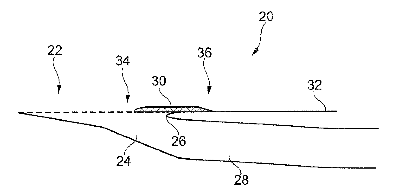
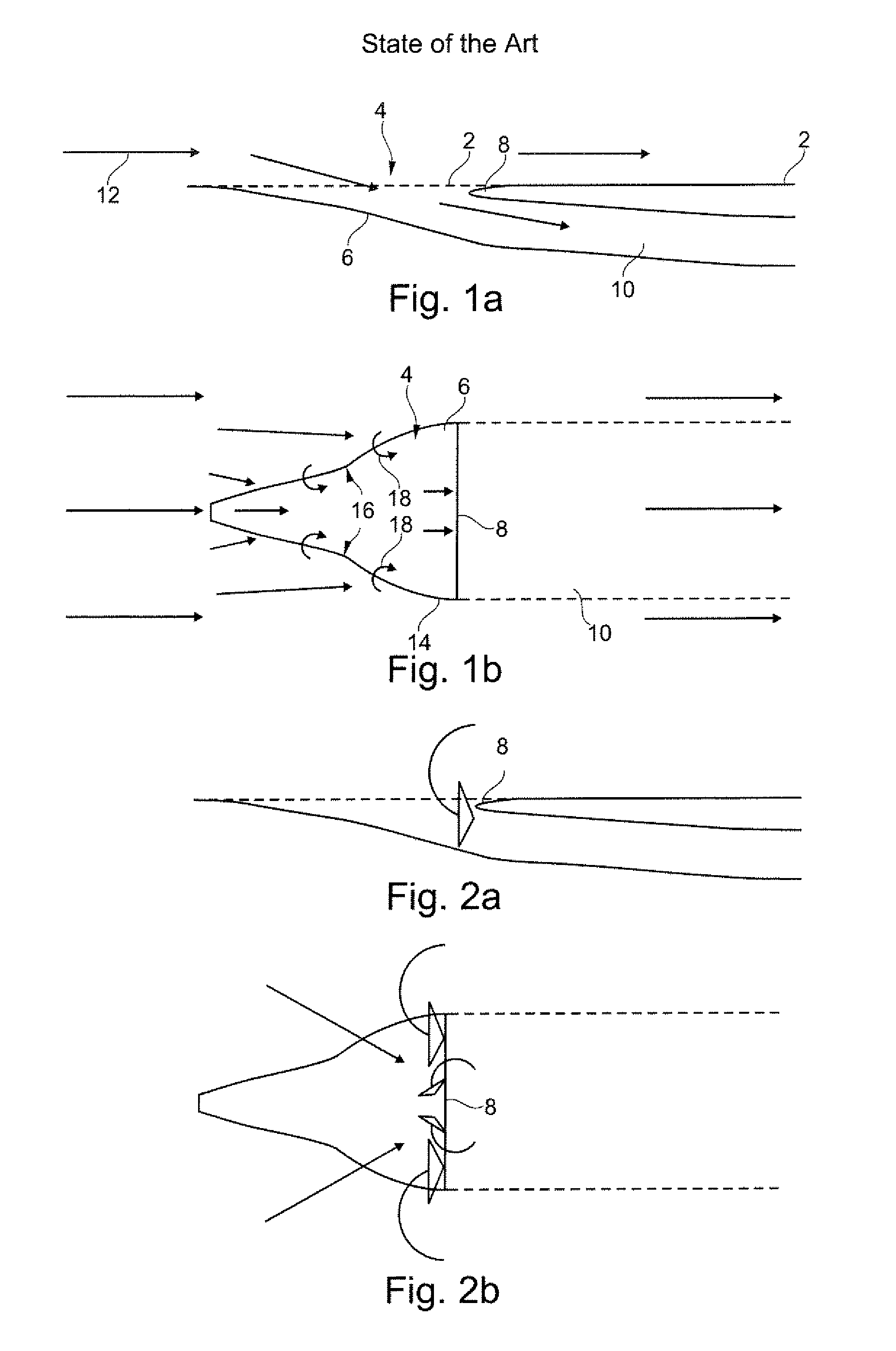
[0023]FIG. 1a shows a lateral section view of a NACA air inlet from the state of the art. In the outer skin 2 there is an opening 4, underneath which a bottom element 6 extends from the outer skin 2 into an interior region of the vehicle. Underneath a border edge 8, which comprises a rounded shape and is thus also referred to as a “lip” between the bottom element 6 and the border edge 8 an air guide channel 10 adjoins which channels air from the surroundings to the respective system. The airstream 12, which in the drawing plane comes from the left-hand side, passes through the opening 4 and in doing so partly enters the air guide channel 10, while only minimally changing the drag of the vehicle.

[0024]FIG. 1b shows a top view of the opening 4. The diagram shows the divergent opening contour 14, wherein the bottom element 6 usually comprises the same contour so that between the opening contour 14 and the bottom element 6 there are walls 16 which extend so as to be essentially perpendi...


PUM


Abstract

The invention relates to an air inlet for a vehicle comprising an opening with an opening contour in an outer skin of the vehicle; at least one bottom element; one or several walls between the opening contour and the bottom element; and an air guide channel with a longitudinal axis, wherein the bottom element extends from the outer skin of the vehicle to an interior region of the vehicle underneath a border edge of the opening, and the air guide channel adjoins from between the bottom element and the border edge, wherein at least one transition region between the opening contour and the walls at least in some regions comprises an essentially convex-shaped profile that essentially extends parallel to the air guide channel. The air inlet according to the invention is in a position to remove air from a flow boundary layer and to provide said air to air-consuming systems.

Description

CROSS-REFERENCE TO RELATED APPLICATIONS[0001]This application claims the benefit of the filing date of U.S. Provisional Patent Application No. 61 / 131,024 filed Jun. 5, 2008, the disclosure of which application is hereby incorporated herein by reference.BACKGROUND OF THE INVENTION[0002]The invention relates to an air inlet for a vehicle, to the use of an air inlet for a vehicle, as well as to a vehicle comprising at least one air inlet.[0003]Various systems in vehicles depend on being supplied with, or cooled with, external air. For example, vehicles are equipped with NACA air inlets in order to supply air conditioning equipment, ventilation systems and cooling systems as effectively as possible with external air. The particular shape of the NACA inlet, also referred to as a NACA duct or NACA scoop, was developed with the aim in aircraft in flight to guide flow that is as high in energy as possible from outside the aerodynamic boundary layer into the inlet, while at the same time inc...

Claims


Application Information

Patent Timeline
IPC IPC(8): B64D33/02F16L9/00
CPCB60H1/26B60H2001/006B60K11/08B61D17/02Y02T50/56B64D13/00B64D2013/0622Y02T30/32B61D27/00Y10T137/0536Y02T30/00Y02T50/50
Inventor SIERCKE, MATTHIASHEISE, ULRICHHOLMGREN, JOAKIMGOMMET, ADELINE
Owner AIRBUS OPERATIONS GMBH
Why Eureka
Try Eureka