Meshed touchscreen pattern

Active Publication Date: 2010-02-25
WACOM CO LTD
View PDF45 Cites 97 Cited by
  • Summary
  • Abstract
  • Description
  • Claims
  • Application Information

AI Technical Summary

Problems solved by technology

In addition, this caused additional problems as the narrow intersections cause high resistance along the conductor.

Method used


Image

  • Meshed touchscreen pattern
  • Meshed touchscreen pattern
  • Meshed touchscreen pattern

Examples


embodiment 200

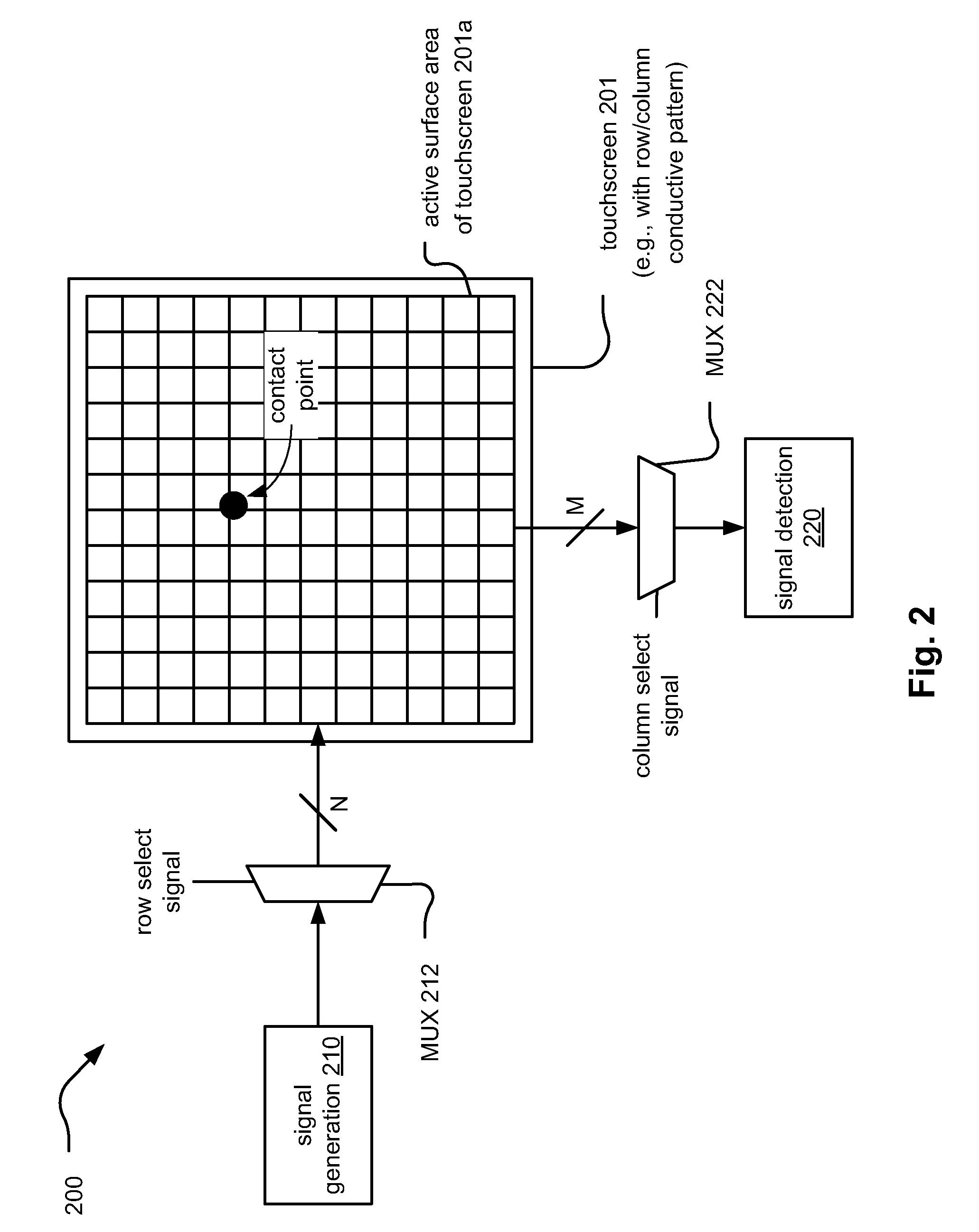
[0068]FIG. 2 illustrates an embodiment 200 of a touchscreen 201 in which cross point detection is performed to locate a user's interaction with the touchscreen. In some embodiments, an active surface area of the touchscreen 201a covers a slightly smaller portion of the touchscreen 200. For example, a border or perimeter around the active surface area of the touchscreen 201a may be employed.

[0069]A number of conductors forming rows and columns of a conductive pattern (e.g., indium tin oxide (ITO) as may be deposited on a substrate composed of polyester or other material) on one or more layers of the touchscreen. In some embodiments, a first portion of the conductive pattern (e.g., the columns) is disposed on a first layer, and a second portion of the conductive pattern (e.g., the rows) is disposed on a second layer; the first and second layer may be separated by a dielectric material in some embodiments. Alternatively, the row and column oriented conductors may be disposed on the sam...

embodiment 300

[0074]FIG. 3 illustrates an embodiment 300 of a touchscreen 301 in which zone detection is performed to location a user's interaction with the touchscreen. As with the previous embodiment, in some embodiments, an active surface area of the touchscreen 301a covers a slightly smaller portion of the touchscreen 300. For example, a border or perimeter around the active surface area of the touchscreen 301a may be employed.

[0075]This embodiment 300 differs from the previous embodiment, at least in that, a signal generation / detection module 310 is employed both to provide a signal to a particular row and to detect a change in the signal being provided to that particular row. The signal generation / detection module 310 operates cooperatively with a MUX 312 to apply a signal and detect that signal being applied to each of the rows and columns of the conductive pattern of the touchscreen.

[0076]When a user does interact with the touchscreen, an increased capacitance will be introduced correspon...

embodiment 400

[0083]Referring to embodiment 400 of FIG. 4, this diagram shows substantially complementary conductors aligned in a direction such that the conductors are spaced as closely to one another as allowed by the processing and manufacturing processes employed to make the touchscreen (i.e., placing adjacent conductors as close to one another as possible). The conductors may be viewed as being implemented in an active surface area of a touchscreen (e.g., where a user has the capability to interact with the touchscreen). The complementary alignment of these conductors indicates that they substantially cover the active surface area of a touchscreen. Of course, the conductors do have sufficient spacing or isolation between them so that they do not directly and electrically contact each other.

[0084]The spacing between the axial centers of adjacent conductors is referred to as the pitch (e.g., row pitch or column pitch when the conductors are aligned in rows or columns, respectively). Also, the ...


PUM


Abstract

Meshed touchscreen pattern. A conductive pattern implemented within a touchscreen (e.g., using indium tin oxide (ITO) such as may be deposited on a substrate composed of polyester or some other material) provides paths for signals traveling through the touchscreen. By monitoring these signal in accordance with some means (e.g., cross point detection, zone detection, etc.) an estimate may be made as to a location of user's interaction with the touchscreen (e.g., finger or stylus touching of the touchscreen). The conductive pattern includes a number of conductors aligned in various directions (e.g., row and column conductors) across the touchscreen, and they are separated by a dielectric layer (e.g., air, SiO2, or any other desirable dielectric layer). The conductors include a great deal of interlacing and meshing as achieved by spurs, extensions, and / or protrusions (e.g., of any desired shape) extending from one conductor into an adjacent conductor within the conductive pattern.

Description

CROSS REFERENCE TO RELATED PATENTS / PATENT APPLICATIONSProvisional Priority Claims[0001]The present U.S. Utility patent application claims priority pursuant to 35 U.S.C. § 119(e) to the following U.S. Provisional Patent Applications which are hereby incorporated herein by reference in their entirety and made part of the present U.S. Utility patent application for all purposes:[0002]1. U.S. Provisional Application Ser. No. 61 / 090,892, entitled “Extended touchscreen pattern,” (Attorney Docket No. 2008LP07US0), filed 08-21-2008, pending.[0003]2. U.S. Provisional Application Ser. No. 61 / 092,914, entitled “Meshed touchscreen pattern,” (Attorney Docket No. 2008LP08US0), filed 08-29-2008, pending.Incorporation by Reference[0004]The following U.S. Utility patent application, being filed concurrently, is hereby incorporated herein by reference in its entirety and is made part of the present U.S. Utility patent application for all purposes:[0005]1. U.S. Utility application Ser. No. ______, ent...

Claims


Application Information

Patent Timeline
Patent Type & Authority Applications(United States)
IPC IPC(8): G06F3/041
CPCG06F2203/04107G06F3/044G06F3/0446G06F3/0443G06F3/0448
Inventor GRAY, MICHAEL S.GRAY, PATRICK T.YAMAMOTO, SADAO
Owner WACOM CO LTD
Why Eureka
Try Eureka