Method and arrangement for three-dimensional representation

a three-dimensional system and display technology, applied in the field of spatial representation, can solve the problems of reducing the brightness of this type of 3-d system in comparison with a 2-d display, lenticular lenses, and high light loss, and achieve the effect of improving the perceptibility of multiple simultaneous viewers

Inactive Publication Date: 2010-02-25
WISE VISION HLDG
View PDF6 Cites 10 Cited by
  • Summary
  • Abstract
  • Description
  • Claims
  • Application Information

AI Technical Summary

Benefits of technology

[0016]It is therefore an object of the present invention to provide a possibility for autostereoscopic representation based on barrier technology to achieve improved perceptibility for multiple simultaneous viewers.

Problems solved by technology

A disadvantage here, as in all barrier methods, is the high light loss.
Lenticular lenses, however, can be produced only in a costly manner and the production process for a 3-D display based thereon is not trivial.
A disadvantage here as well, however, is the greatly reduced brightness of this type of 3-D systems in comparison with a 2-D display.
Nevertheless, this approach involves a high adjustment effort and is only extremely difficult to implement for larger screen diagonals (from about 25 inches).
The embodiments and teaching disclosed in this publication, however, usually produce unpleasant moiré effects and / or a greatly limited depth perception, because the stereo contrast is greatly reduced, compared with, for instance, the teaching of JP 08-331605 AA.

Method used


Image

  • Method and arrangement for three-dimensional representation
  • Method and arrangement for three-dimensional representation
  • Method and arrangement for three-dimensional representation

Examples


Embodiment Construction

[0049]The drawings are not to scale. This refers in particular also to the angular dimensions.

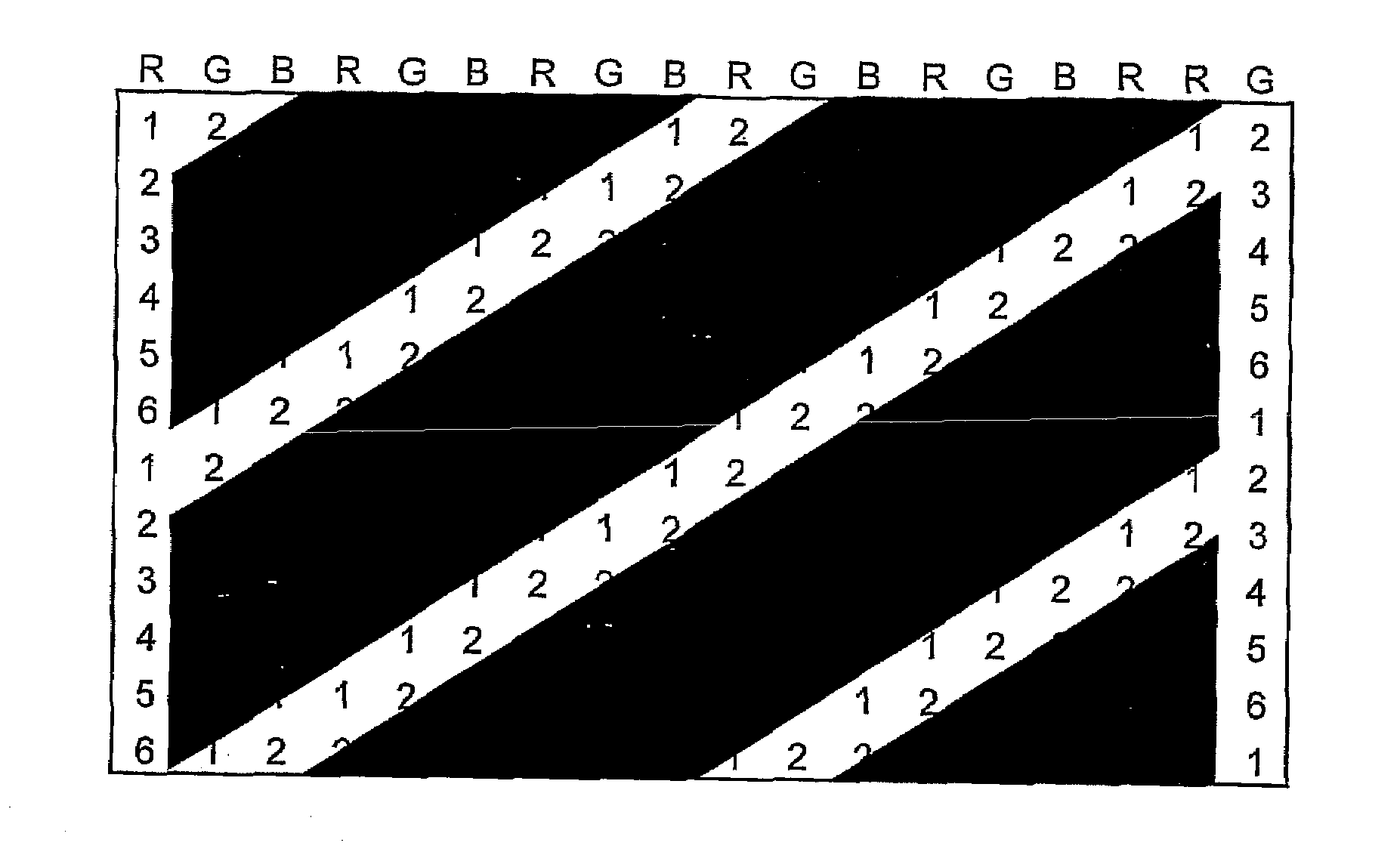
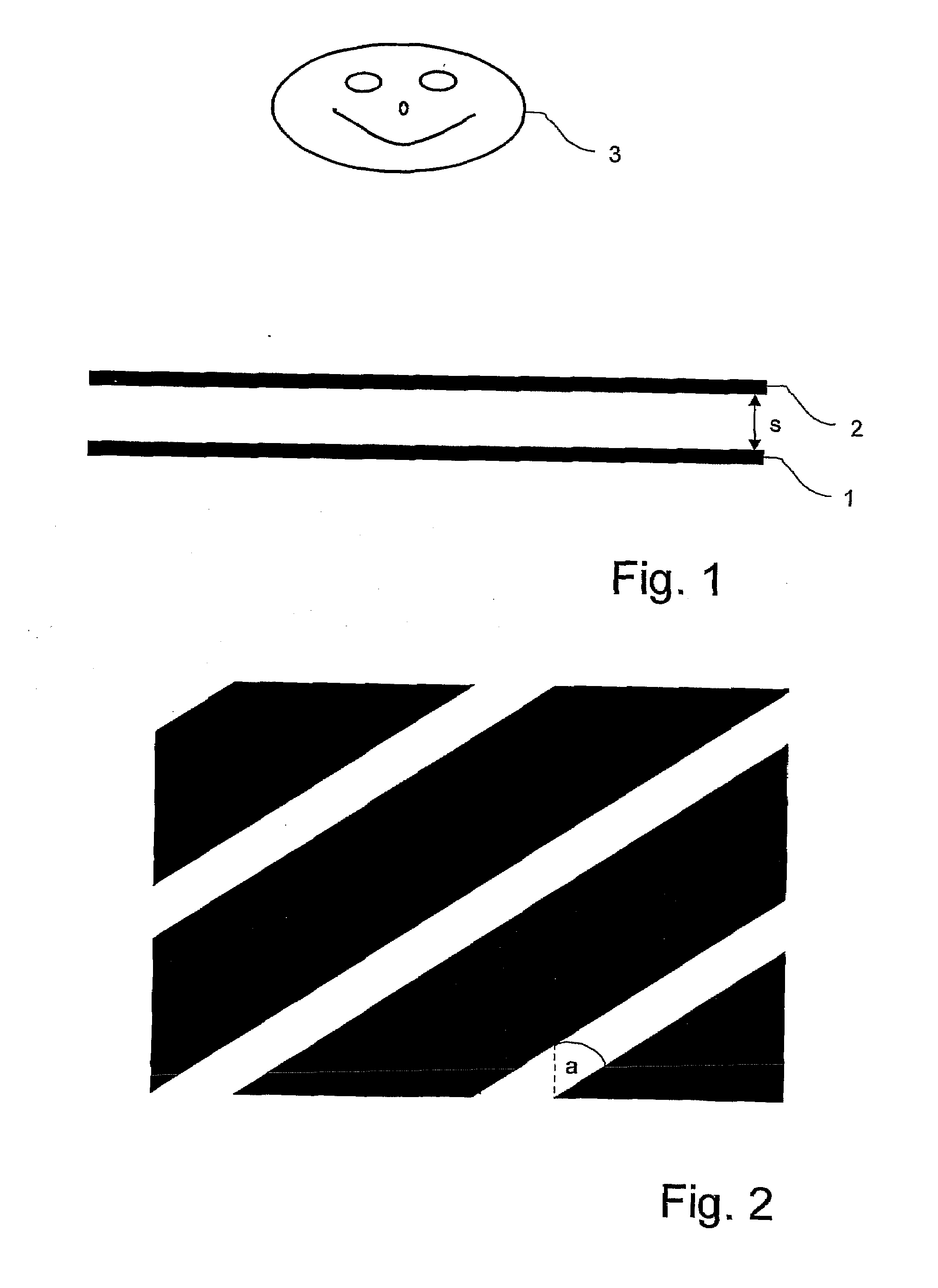
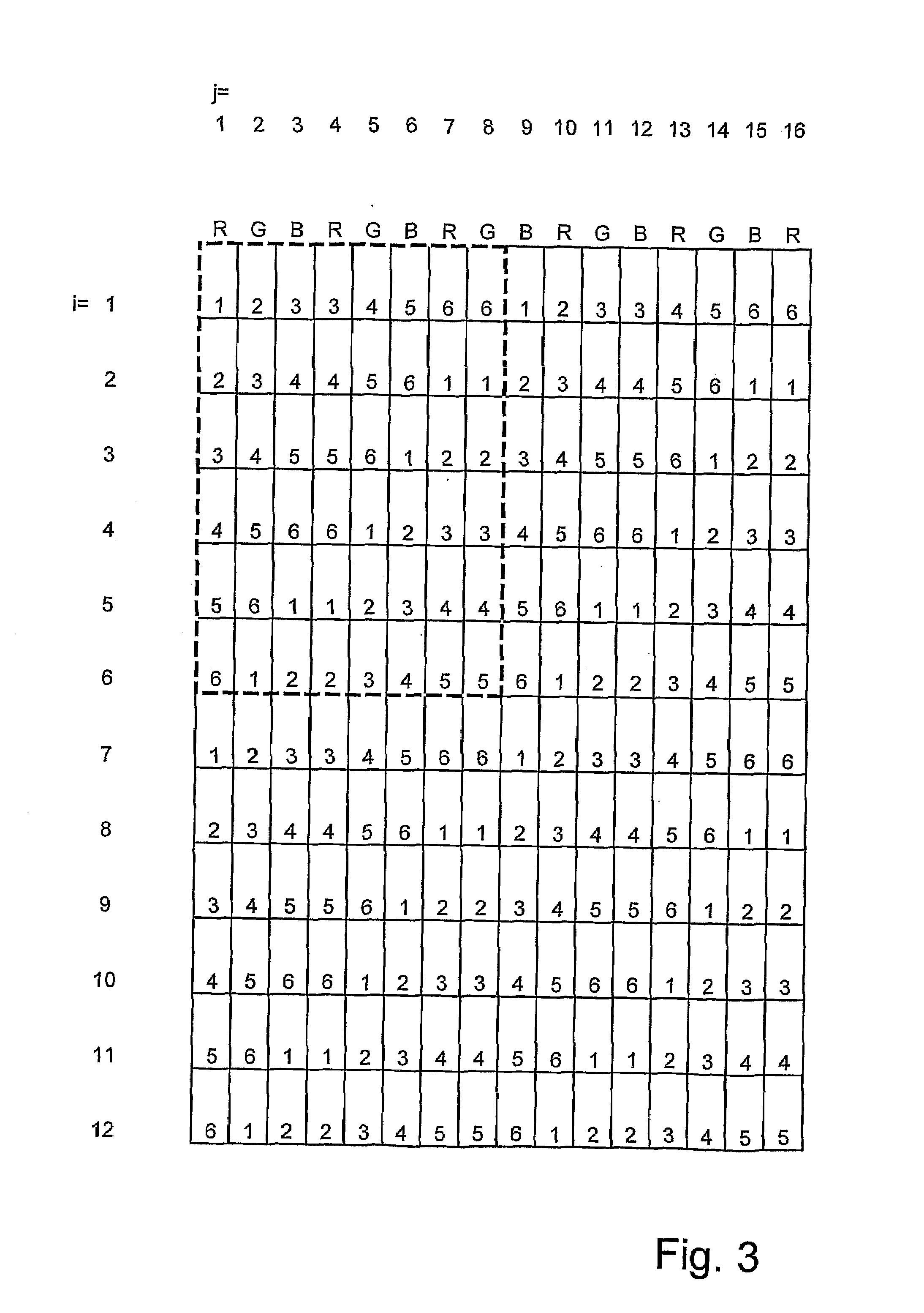
[0050]FIG. 1 shows a schematic structure for realizing the method of the invention. This includes a grid 1 of image elements x(i,j), on which image section data of different viewpoints A(k) with k=1, . . . , n and n=6 or n=7 are made visible, and a parallax barrier screen 2 placed before grid 1 of image elements x(i,j) at the distance s in viewing direction of a viewer 3. Of course, there can also be several viewers 3 who-obtain a spatial impression based on the method of the invention.

[0051]FIG. 2 shows a section of a parallax barrier screen 2 for use in the method of the invention. This parallax barrier screen 2 contains alternately opaque and transparent sections, whereby the transparent sections according to the invention correspond substantially to straight bordered lines, which in parallel projection of parallax barrier screen 2 onto grid 1 of image elements x(i,j) are inclined by at ...


PUM


Abstract

The invention relates to the field of spatial representation, particularly to images which are spatially perceivable for simultaneous multiple viewers without auxiliary devices so-called autostereoscopic visualization. The invention addresses the problem of creating a form of autostereoscopic representation based on barrier technology in order to achieve an improved perceptibility for multiple simultaneous viewers. This problem is solved by a method for spatial representation wherein image section data of different viewpoints A(k), where k=1, . . . , n and n=6 or n=7, are made visible on a grid of image elements x(i,j), and at least one parallax barrier screen containing alternating opaque and transparent sections is placed at a distance before or behind the grid of image elements x(i,j). The transparent sections substantially correspond to straight bordered lines which, during the parallel projection of parallax barrier screens onto the grid of image elements x(i,j), are inclined to at least 21 degrees with respect to the vertical direction of the grid of image elements x(i,j) and, furthermore, each have the width of at least 1.9 image elements x(i,j) in the horizontal direction of the grid of image elements x(i,j).

Description

[0001]This nonprovisional application is a continuation of International Application No. PCT / DE2007 / 002136, which was filed on Nov. 26, 2007, and which claims priority to German Patent Application No. DE 10 2007 016 773.5, which was filed in Germany on Apr. 4, 2007, and which are both herein incorporated by reference.BACKGROUND OF THE INVENTION[0002]1. Field of the Invention[0003]The invention relates to the field of spatial representation, specifically to the representation spatially perceptible without aids for simultaneous multiple viewers, the so-called autostereoscopic visualization.[0004]2. Description of the Background Art[0005]There have been approaches for some time to the aforementioned field. A pioneer in this field was Frederic Ives, who in the publication GB190418672 A proposed a system with a “line screen” for 3-D imaging. Further, fundamental findings on the use of barrier screens for 3-D imaging are described in the publication by Sam H. Kaplan “Theory of parallax ba...

Claims


Application Information

Patent Timeline
Patent Type & Authority Applications(United States)
IPC IPC(8): G02B27/22
CPCH04N13/0409H04N13/0415H04N13/0411H04N13/312H04N13/31H04N13/317
Inventor OTTE, STEPHANKLIPPSTEIN, MARKUS
Owner WISE VISION HLDG
Why Eureka
Try Eureka