Optical system and method for managing brightness contrasts between high brightness light sources and surrounding surfaces

a technology of optical system and brightness contrast, applied in the field of illumination and lighting systems, can solve problems such as visual discomfort, and achieve the effect of reducing brightness contrast and observing brightness contras

Active Publication Date: 2010-02-25
ABL IP HLDG
View PDF17 Cites 37 Cited by
  • Summary
  • Abstract
  • Description
  • Claims
  • Application Information

AI Technical Summary

Benefits of technology

[0005]The present invention involves an optical system and method for providing at least one, and preferably an array of high brightness light sources with a surrounding structure that captures and re-emits a portion of the light from the individual high-brightness light sources. The re-emitted light creates brightness in surfaces that surround the high brightness light sources and reduces observable brightness contrasts. The light source surround structure is provided in the form of one or more light waveguides in a plane (which could be flat or curved) having at least one and preferably an array of source light openings into which or behind which high brightness light sources are placed and through which a portion of

Problems solved by technology

Such brightness contrasts can produce visual discom

Method used


Image

  • Optical system and method for managing brightness contrasts between high brightness light sources and surrounding surfaces
  • Optical system and method for managing brightness contrasts between high brightness light sources and surrounding surfaces
  • Optical system and method for managing brightness contrasts between high brightness light sources and surrounding surfaces

Examples


Embodiment Construction

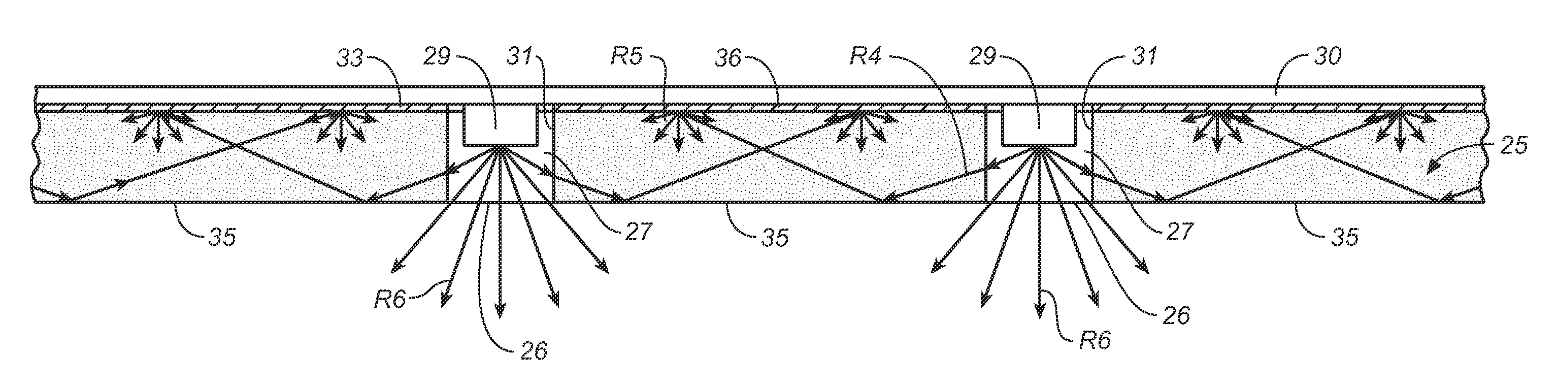
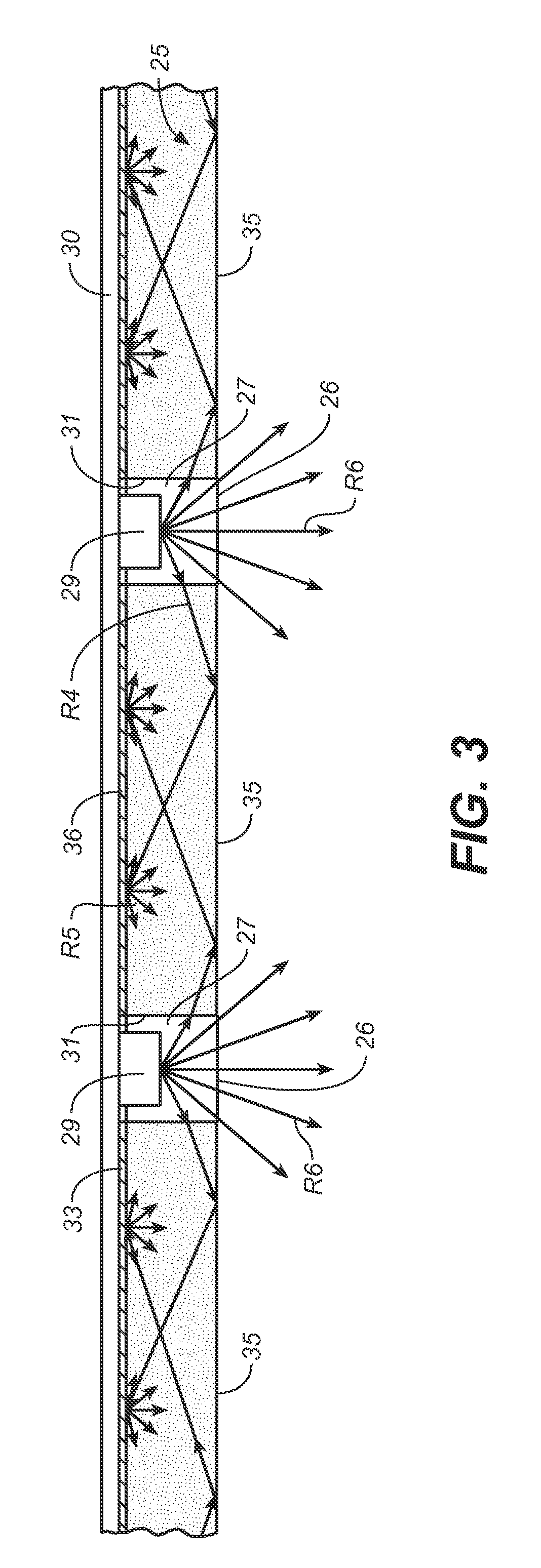
[0029]The present invention involves the management of the often extreme brightness contrasts that exist between small high brightness light sources, such as LEDs, and surfaces that surround the light sources. As used herein, the term “high brightness” means ranges of brightness typically produced by LEDs. While LEDs are referred to throughout this description, it shall be understood that the invention is not limited to the use of LEDs, but could employ other small commercially available light sources, such as plasma light sources, that exhibit similar levels of brightness. The management of surround surface brightness is uniquely achieved in the invention using light waveguides.

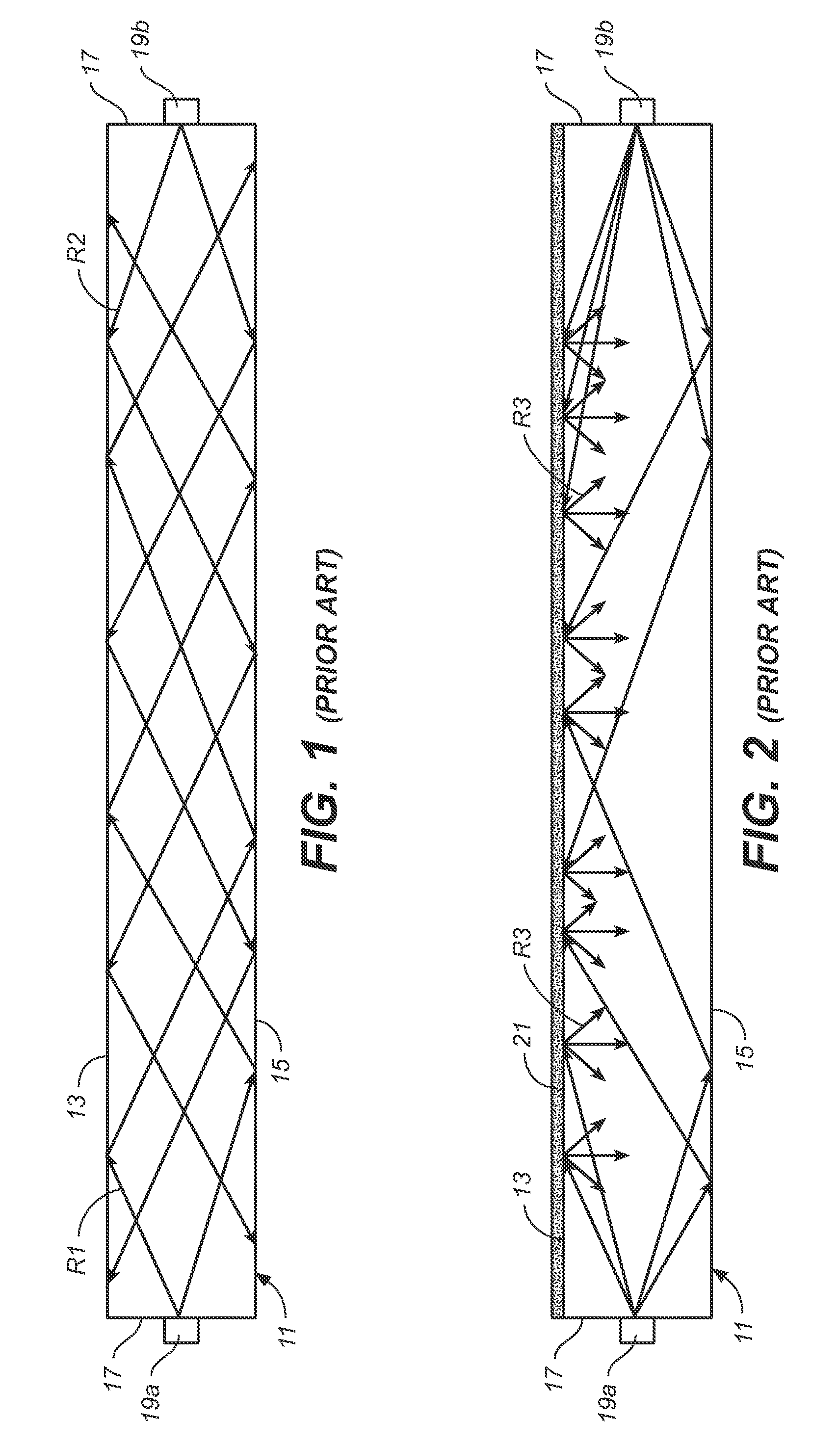
[0030]FIGS. 1 and 2 generally illustrate the principle of the light waveguide used in the invention. Light waveguides, also sometimes referred to as “light guides” or “light pipes,” are well known. The light waveguide works on the principle of internal reflections governed by Snell's Law, and permits light i...


PUM


Abstract

An optical system and method provides at least one, and preferably an array of relatively small, high brightness light sources with a surrounding surface that exhibits brightness, thereby reducing the contrast between the high brightness produced by the light sources and the brightness of their surrounding surfaces. The optical system includes a light waveguide structure that captures a portion of the light from the individual high-brightness light sources, and then re-emits the source light to create brightness in the light sources' surrounding surfaces. The optical system is particularly adapted for use with LEDs, but could be used with other high brightness light sources.

Description

CROSS-REFERENCE TO RELATED APPLICATIONS[0001]This application claims the benefit of U.S. provisional application No. 61 / 068,066 filed Mar. 3, 2008.BACKGROUND OF INVENTION[0002]The present invention generally relates luminaires and lighting systems for providing general and specialty lighting, and more particularly to luminaires and lighting systems employing light sources that are relatively bright, such as light emitting diodes (LEDs).[0003]LEDs are increasingly used in lighting applications because of their energy efficiency, that is, their ability to produce a given lumen output per watt consumed. Such light sources are relatively small and intensely bright. For example, an LED that is rated at just ⅛ watt and that produces 30 lumens per watt can have a brightness of between approximately 50,000 to 300,000 candelas per square meter for LED sizes ranging from 25 mm2 down to 4 mm2. For LEDs having higher wattage ratings the brightness increases dramatically.[0004]Often LED are empl...

Claims


Application Information

Patent Timeline
IPC IPC(8): F21V1/00
CPCF21S8/086F21W2131/103F21Y2101/02F21Y2105/001F21Y2105/00G02B6/0055G02B6/0068F21V5/02G02B6/0021F21Y2105/10F21Y2115/10
Inventor NGAI, PETER Y.Y.
Owner ABL IP HLDG
Why Eureka
Try Eureka