Micropump

a micro-pump and pump body technology, applied in the direction of flexible member pumps, machines/engines, positive displacement liquid engines, etc., can solve the problems of reducing the thickness of the structure, reducing the restoration ability of the tube, and reducing the delivery accuracy, so as to achieve the effect of increasing the reliability

Inactive Publication Date: 2010-02-25
SEIKO EPSON CORP
View PDF79 Cites 86 Cited by
  • Summary
  • Abstract
  • Description
  • Claims
  • Application Information

AI Technical Summary

Benefits of technology

[0090]According to this structure, the battery can be replaced at the time of replacement

Problems solved by technology

Thus, the thickness of the structure is difficult to be reduced.
Thus, restoration ability of the tube lowers, and delivery accuracy decreases.
Furthermore, in the structure which stacks the pump module and the motor module on each other for connection to transmit the rotational driving force of the step motor to the rotor by tooth engagement between the pinion and the gear as the connection elements, the connecting and coupling structure becomes complicated, and assembly becomes difficult.
It is considered that delivery accuracy lowers due to deterioration of restoration of the tube after the tube is kept closed with pressure for a long period.
As explained above, it is difficult to form the continuous side wall of the tube guide groove on the fingers side.
During p

Method used


Image

  • Micropump
  • Micropump
  • Micropump

Examples


first embodiment

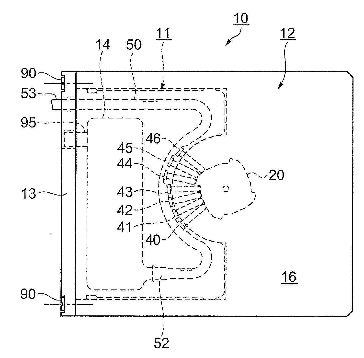
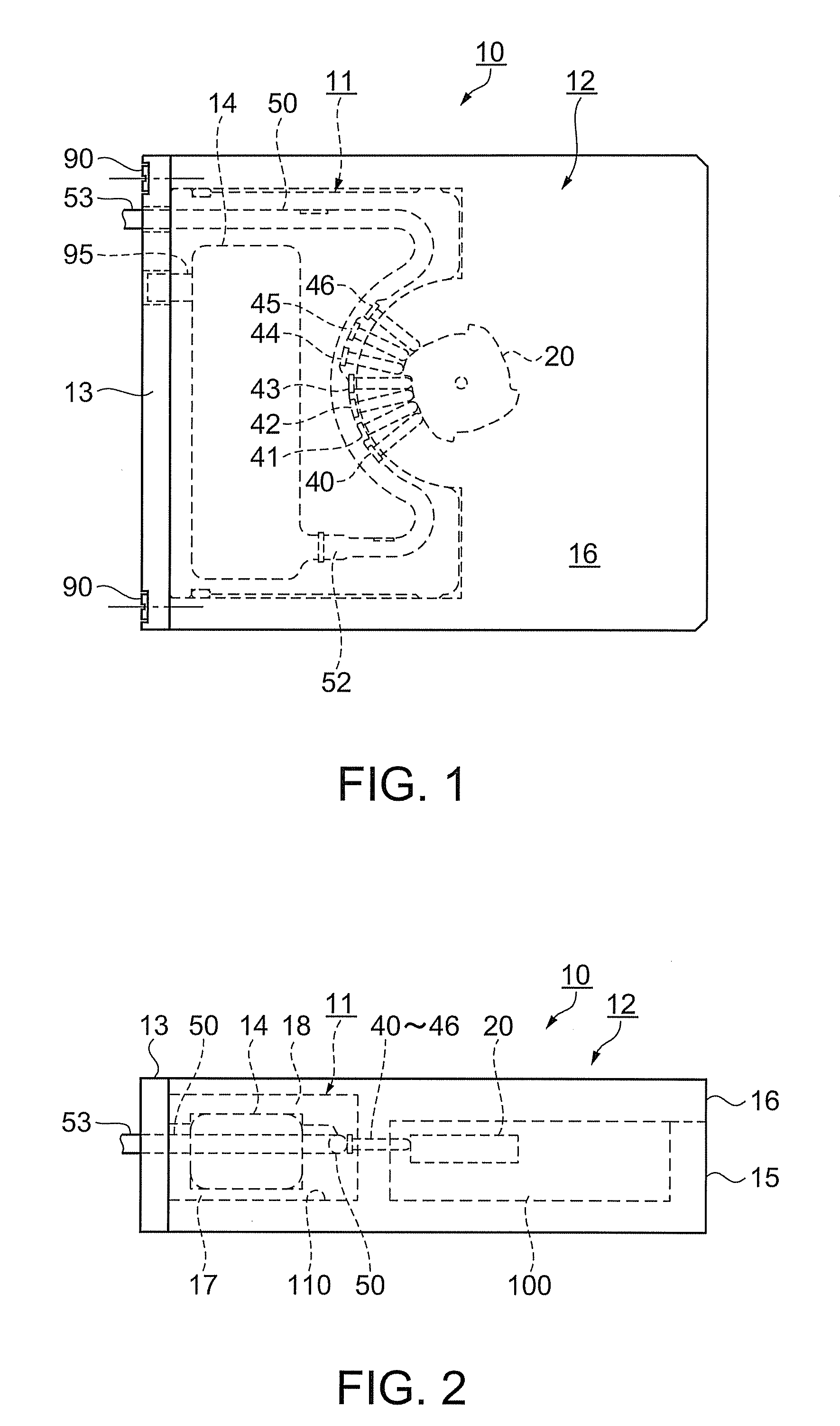
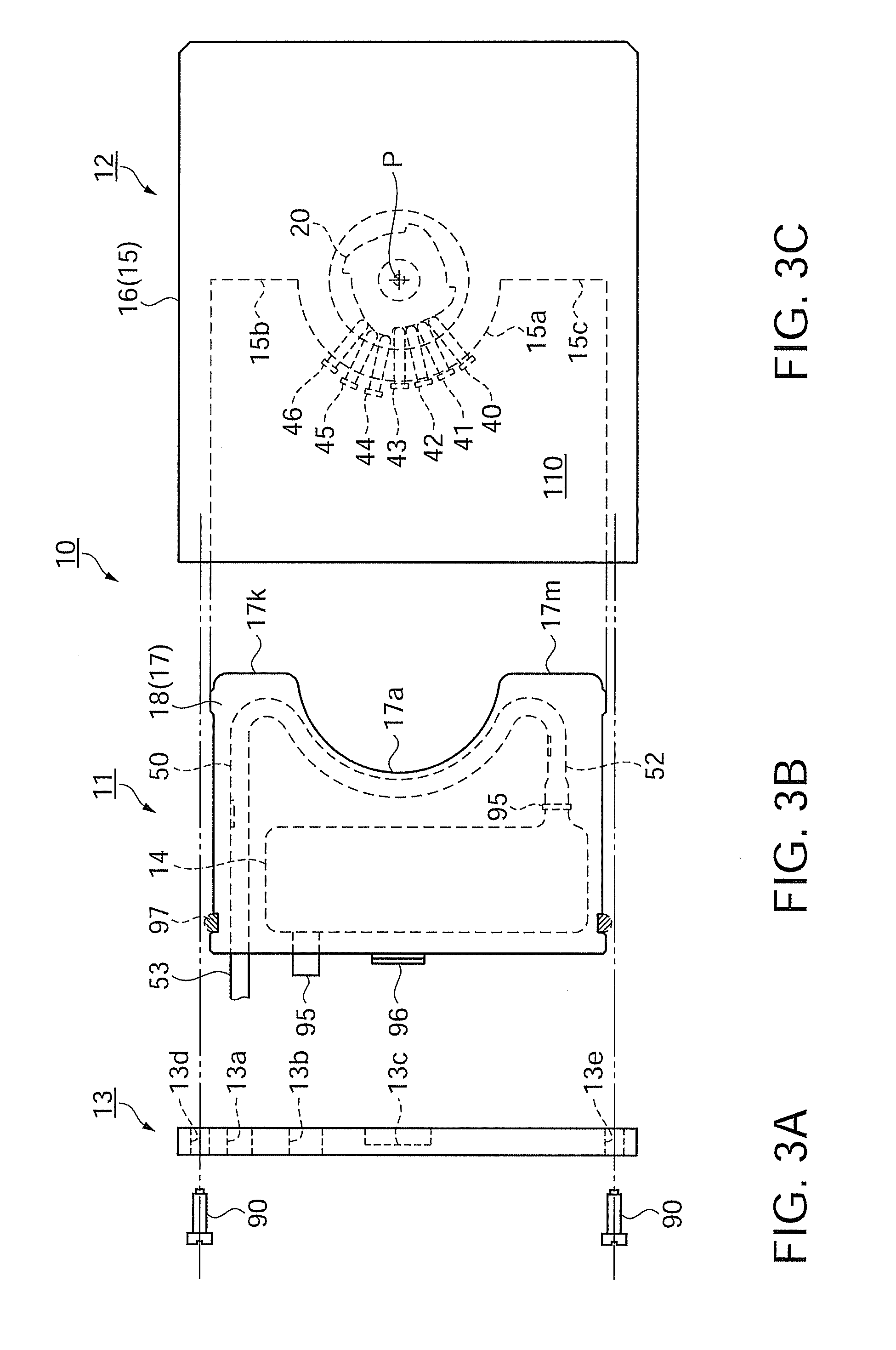
[0107]FIG. 1 is a plan view illustrating a general appearance of a micropump according to the first embodiment. FIG. 2 is a front view illustrating the general appearance of the micropump in this embodiment. As shown in FIGS. 1 and 2, a micropump 10 is a one-piece device produced by slidingly inserting a tube unit 11 through an opening formed on the left side surface of a control unit 12 as viewed in the figure and fixing the tube unit 11 to the control unit 12 by a fixing frame 13 as a cover member using fixing screws 90.

[0108]The tube unit 11 has a tube 50 having elasticity and a circular-arc part, a first tube guide frame 17 and a second tube guide frame 18 as tube guide frames for holding the tube 50, and a reservoir 14 communicating with an inlet port 52 of the tube 50 to contain fluid. In the following explanation, the fluid is liquid such as liquid medicine.

[0109]The control unit 12 has a cam 20, a motor and a transmission mechanism (not shown) as a drive unit for giving rota...

second embodiment

[0196]A micropump according to a second embodiment is hereinafter described with reference to the drawings. In the second embodiment, a plurality of fingers have a separation preventing mechanism for preventing separation of the fingers from the control unit 12. In the following explanation, the difference from the first embodiment is chiefly touched upon. Since the fingers 40 through 46 have the same shape, only the finger 43 is discussed as an example.

[0197]FIGS. 8A and 8B are cross-sectional views illustrating a part of the micropump in the second embodiment. FIG. 8A shows a first example, and FIG. 8B shows a second example.

[0198]The first example is now described with reference to FIG. 8A. The first device frame 15 has a finger guide hole 85 into which the finger 43 is inserted. The finger guide hole 85 is formed by sealing the upper opening of the groove 15h of the first device frame 15 by the second device frame 16 similarly to the structure shown in FIG. 6B.

[0199]The finger 4...

third embodiment

[0210]A micropump according to a third embodiment is now discussed with reference to the drawings. In the third embodiment, the first tube guide frame 17 has a tube guide groove 17c into which the tube 50 is inserted, and a tube supporting member for supporting the tube 50. In the following explanation, the difference from the first embodiment is chiefly touched upon.

[0211]FIGS. 9A through 9C illustrate the micropump in the third embodiment. FIG. 9A is a plan view illustrating a part of the micropump, FIG. 9B is a cross-sectional view taken along a line B-B in FIG. 9A, and FIG. 9C is a cross-sectional view taken along a line D-D in FIG. 9A. A first example is initially discussed.

[0212]As illustrated in FIGS. 9A and 9B, the first tube guide frame 17 has the tube guide groove 17c into which the tube 50 is inserted. It is difficult to form a continuous side wall on the tube guide groove 17c along the tube 50 in the direction of the fingers 40 through 46 for advance and retreat movement...


PUM


Abstract

A micropump includes: a tube unit which includes a tube having elasticity and a circular-arc-shaped part and a tube guide frame for holding the tube; a control unit which has a plurality of fingers extending from the center of the circular-arc shape of the tube in the radial directions, a cam for sequentially pressing the plural fingers from the inlet side to the outlet side of the tube, a drive unit for giving rotation force to the cam, a control circuit unit for controlling operation of the drive unit, a device frame for holding the plural fingers, the cam, the drive unit, and the control circuit unit; a reservoir communicating with an inlet port of the tube; and a power source for supplying power to the control circuit unit, wherein the tube unit is detachably attached to the control unit substantially in the horizontal direction with respect to the rotation surface of the cam and attached to the inside of a space produced by the device frame.

Description

BACKGROUND[0001]1. Technical Field[0002]The present invention relates to a micropump having a tube unit and a control unit attachable to and detachable from each other.[0003]2. Related Art[0004]A wriggling pump is known as a device for transporting liquid at low speed. Recently, such a wriggling pump which rotates a rotor having a plurality of rollers by a step motor as a driving source has been proposed. According to this pump, the rotor rotates along a flexible tube while revolving the plural rollers to suck and deliver liquid (for example, see Japanese Patent No. 3177742).[0005]This type of pump includes a pump module having a tube and a rotor for closing the tube with pressure, and a motor module having a step motor and an output gear mechanism stacked on each other. The pump further includes a gear as a connection element disposed on a rotation shaft of the rotor, and a pinion as a power extracting mechanism disposed on the output gear mechanism. When the pump module and the mo...

Claims


Application Information

Patent Timeline
IPC IPC(8): F04B43/12
CPCF04B43/1261F04B43/082F04B43/1276F04B43/1284
Inventor MIYAZAKI, HAJIMEKAWASUMI, KAZUO
Owner SEIKO EPSON CORP
Why Eureka
Try Eureka