
Device for contact molecular sampling

a technology of molecular sampling and contact molecular structure, which is applied in the field of contact molecular sampling devices, can solve the problems of deteriorating biological integrity and inability to always be used

Inactive Publication Date: 2010-02-25
COMMISSARIAT A LENERGIE ATOMIQUE ET AUX ENERGIES ALTERNATIVES
View PDF1 Cites 7 Cited by
  • Summary
  • Abstract
  • Description
  • Claims
  • Application Information

AI Technical Summary

Benefits of technology

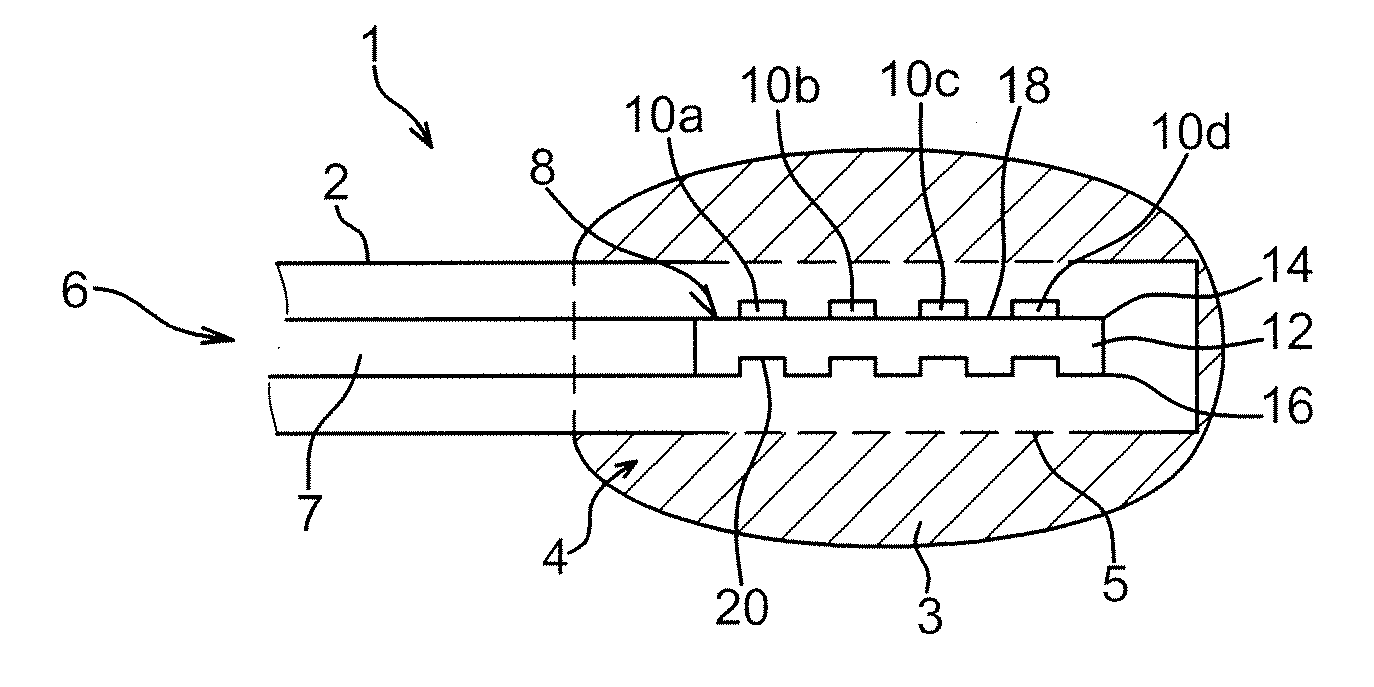
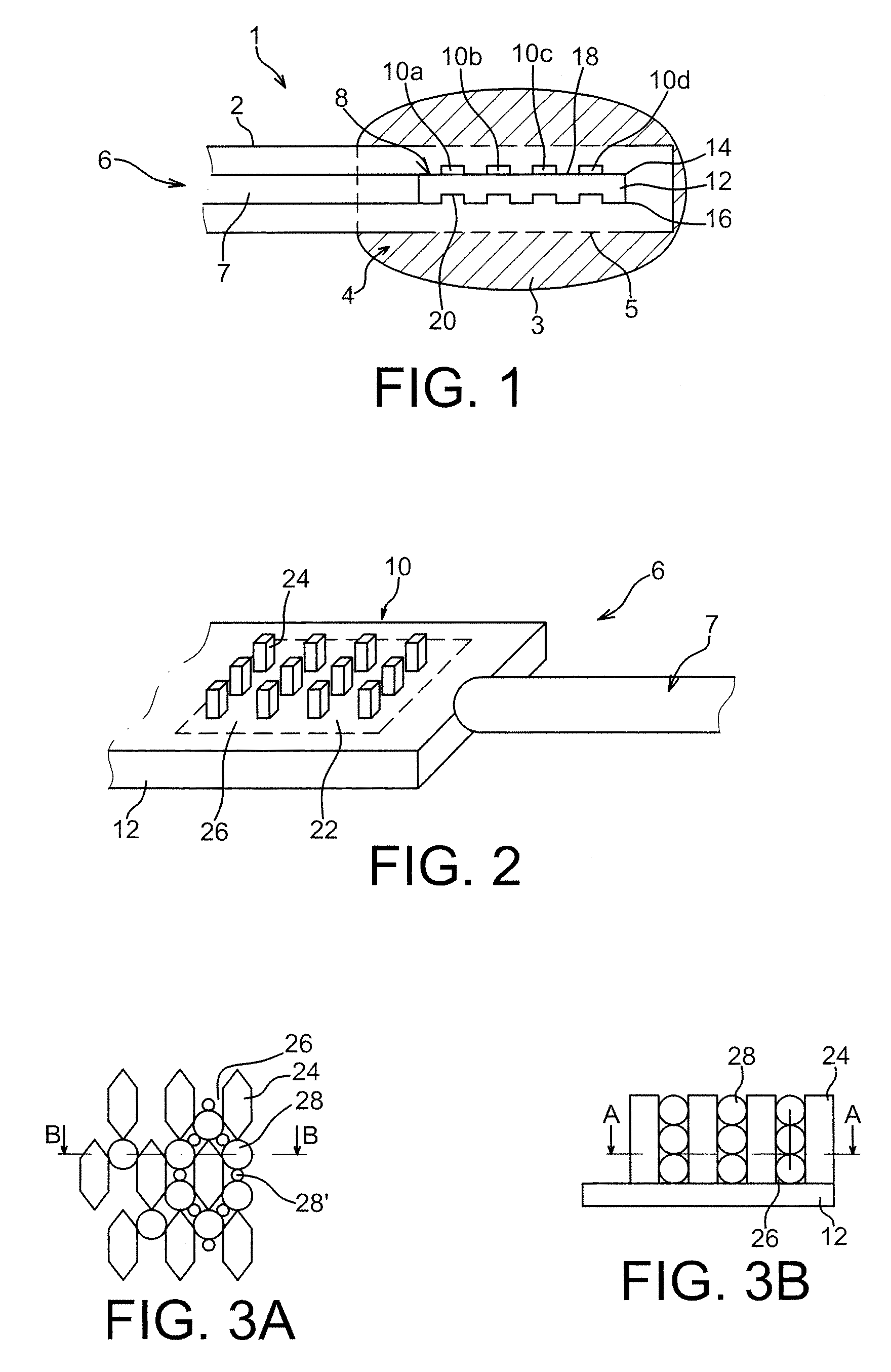
[0009]The invention therefore proposes using mere contact to sample molecules of biological interest: an imprint of the tissue is obtained on a device of the invention, and the molecules collected in this manner in a capture zone of the device can then be analysed. In particular, since the device of usually planar shape is of small size, the developed surface area of the capture zone of the device of the invention is increased, which means that the quantity of trapped target molecules is sufficient to permit efficient, subsequent analysis.
[0015]Various embodiments are provided for the capture zones. The capture zones comprise a bottom wall which may delimit a cavity. To increase the developed surface area, the bottom wall may serve as base for microbeads held in position by a semi-permeable membrane, and / or it may have protuberances.
[0018]The device of the invention is preferably associated with a manipulating rod and a guide sleeve so that it can be accurately positioned inside the tissue to be analysed. In particular, the sleeve may comprise means allowing the capture zones to be placed in contact with the surrounding medium only when the device is in place.

Problems solved by technology

These techniques therefore deteriorate biological integrity; in addition, they cannot always be used especially as the very insertion of a sampling device must be minimal in some areas, in particular in the brain.

Method used


Image

  • Device for contact molecular sampling
  • Device for contact molecular sampling
  • Device for contact molecular sampling

Examples


example of embodiment

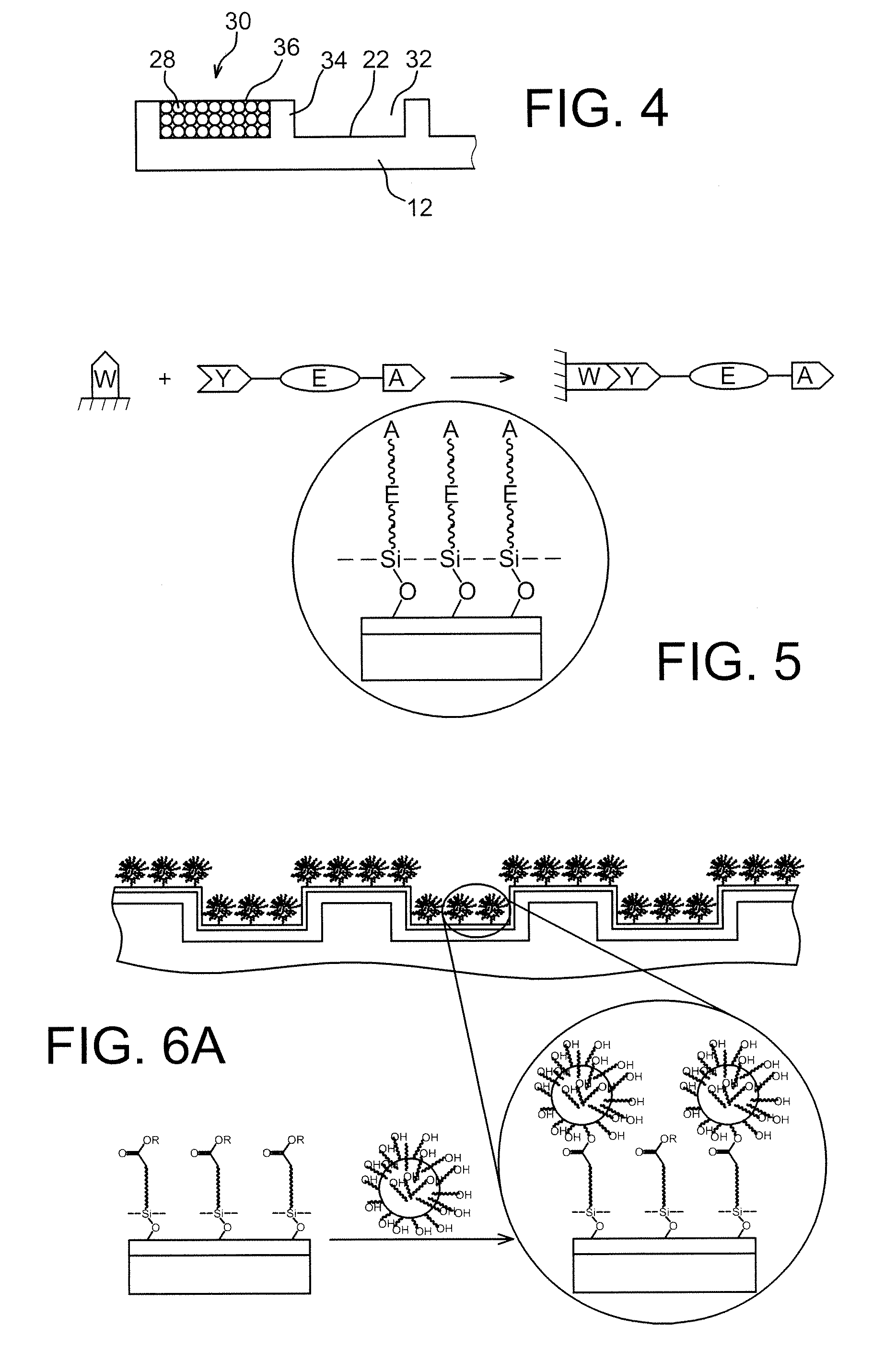
[0091]The preceding device P (support 12 in Si 600×300 μm2, with octagonal protuberances 24) was silanised then functionalised to yield the carboxylate function. At physiological pH, the biological systems and in particular the proteins are naturally charged; the ion interactions (based on chromatographic principles) can be used for the specific absorption of the protein markers. For the anionic surfaces (negatively charged) carboxylate derivatives are the most frequently used.

[0092]The carboxylate and silane functions being incompatible, a strategy of indirect synthesis via the methyl ester of trimethoxysilylundecan-10-oic acid was chosen.

[0093]The acid function is protected in the form of a methyl ester after reaction of the undecenoic acid with sulfuric acid and methanol; the incorporation of the silylated group is conducted conventionally via a hydrosilylation reaction.

[0094]For example, a methyl ester of 10-undec-1-enoic acid is produced to form the methyl ester of trimethoxysi...


PUM


Abstract

A device (6) to sample molecules of biological interest is described. The device (6) includes capture zones (10) whose developed surface area is much greater than the surface so that sampling by contact allows a sufficient quantity of molecules to be obtained to achieve reliable analysis, whilst being sized so that the device (6) is neither invasive nor aggressive.In particular, the device comprises tiered capture zones (10) located on a support (12) fabricated using microtechnology techniques; the capture zones (10) may advantageously be functionalised.

Description

TECHNICAL AREA[0001]The invention concerns the area of non-invasive clinical diagnosis and / or treatment follow-up. More particularly, the invention relates to a microscopic sampling device to sample molecules of biological interest by contact, which does not require any ablation or biopsy and whose architecture is such that its insertion does not cause any damage to surrounding tissue. The invention is particularly suitable for proteomics or genomics.[0002]The invention also concerns a method with which it is possible to determine the protein composition of the different layers of a tissue. In particular, this method is suitable for the mapping of tumours, e.g. brain tumours.STATE OF THE PRIOR ART[0003]In the same way as surgery is tending to be increasingly less invasive, clinical diagnosis and treatment follow-up techniques are tending towards miniaturisation of the tools needed for the various sampling and control operations.[0004]Progress in imaging has largely contributed towar...

Claims


Application Information

Patent Timeline
Patent Type & Authority Applications(United States)
IPC IPC(8): A61B10/04
CPCA61B10/02A61B2010/0216A61B10/04A61B10/0291
Inventor CAILLAT, PATRICEMARTIN, FRANCKCOSNIER, MARIE-LINE
Owner COMMISSARIAT A LENERGIE ATOMIQUE ET AUX ENERGIES ALTERNATIVES
Learn More