
Energy-Saving System for Electronic Apparatus

a technology of energy-saving system and electronic equipment, which is applied in the direction of liquid/fluent solid measurement, instruments, high-level techniques, etc., can solve the problems of user's electricity fees, large amount of electrical energy in standby mode, and even up to 20 w of electrical energy consumption

Inactive Publication Date: 2010-02-25
MATRIXVIXION TECH
View PDF5 Cites 21 Cited by
  • Summary
  • Abstract
  • Description
  • Claims
  • Application Information

AI Technical Summary

Benefits of technology

[0007]Regarding to the aforementioned defects found in prior art, the objective of the present invention is to provide an energy-saving system for electronic apparatus, so as to solve the problem for high energy consumption of prior art electronic apparatus in standby mode.
[0010]As the descriptions set forth hereinbefore, the energy-saving system for electronic apparatus according to the present invention allows disconnection of power energy supplied by the power supply, thus accordingly enabling zero power consumption therein, except that the power-saving module may still need to consume simply about 0.1 Watts of electrical energy in standby mode for uses of power-on signal reception and so on, thereby achieving the effect of power-saving.

Problems solved by technology

For worse circuit designs, such energy consumption may reach even up to 20 W of electrical energy.
As a result, prior art electronic systems, although even rarely utilized, still undesirably consume a large amount of electrical energy in standby mode, making users have to pay a big but unnecessary sum of electricity fees, no matter frequently or infrequently operating the electronic apparatus.

Method used


Image

  • Energy-Saving System for Electronic Apparatus
  • Energy-Saving System for Electronic Apparatus
  • Energy-Saving System for Electronic Apparatus

Examples


Embodiment Construction

[0014]Several embodiments of the energy-saving system for electronic apparatus according to the present invention will now be described in details with reference to the appended drawings.

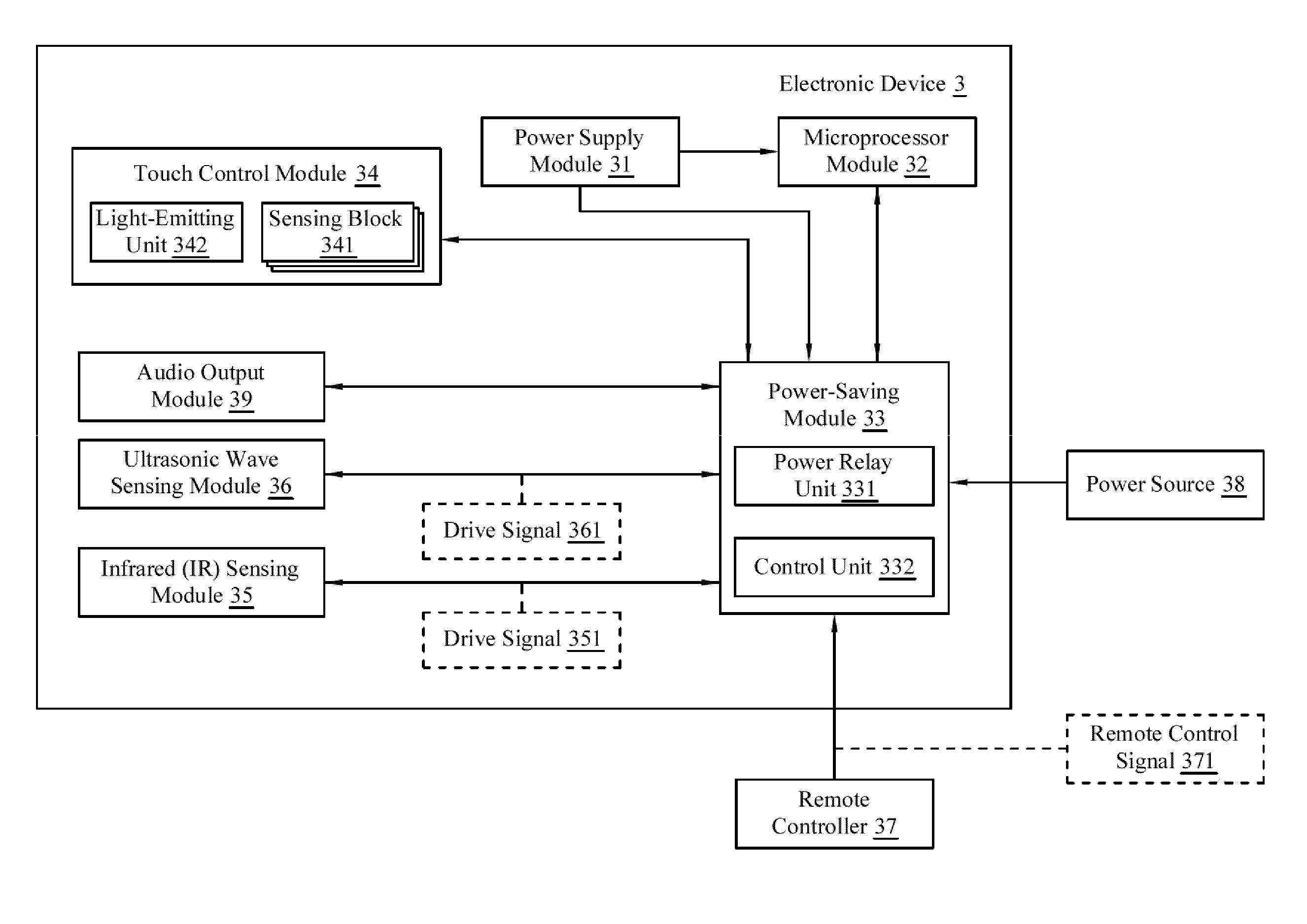
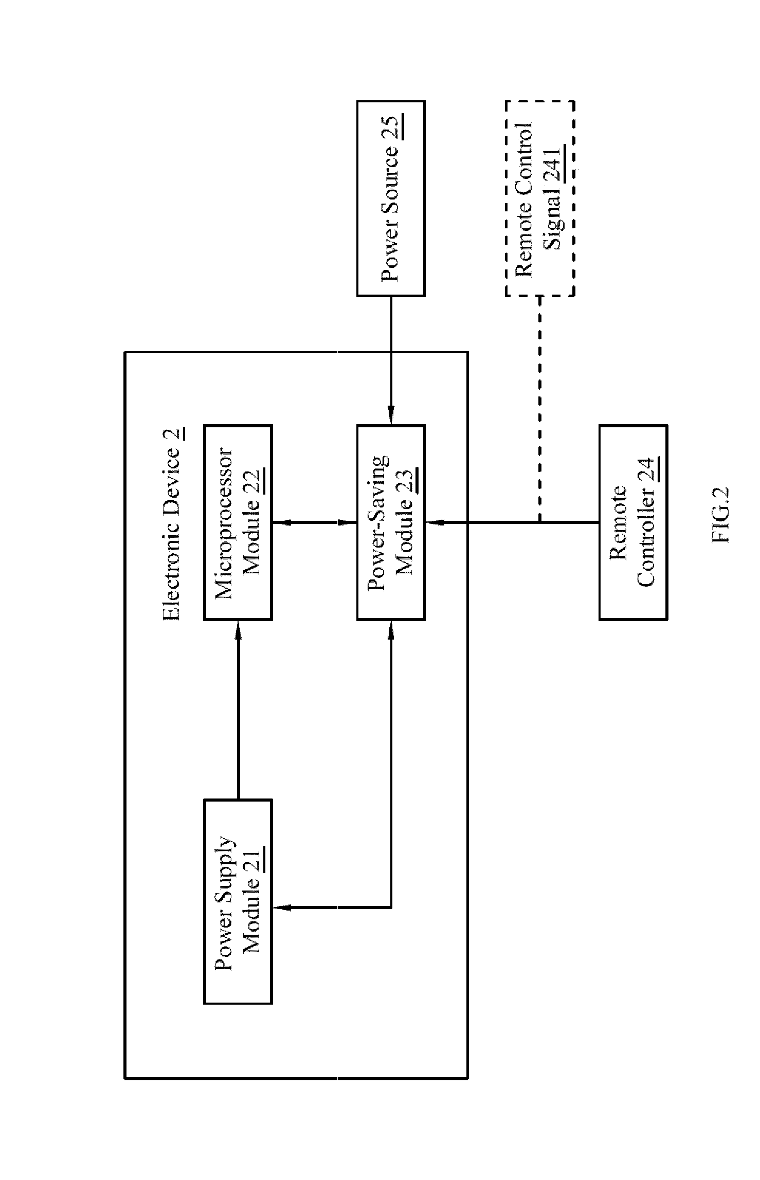
[0015]Refer first to FIG. 2, wherein a block diagram of the energy-saving system for electronic apparatus according to the present invention is shown. In the Figure, the energy-saving system for electronic apparatus is depicted as comprising an electronic device 2 and a remote controller 24. The electronic device 2 includes a power supply module 21, a microprocessor module 22 and a power-saving module 23. Herein the electronic device 2 is implemented as a television in the present embodiment, but it is by no means limited thereto. For example, the electronic device 2 may be an electronic apparatus such as an air conditioner, a heater, a stereo or an audio / video player etc.

[0016]The microprocessor module 22 is electrically connected to the power supply module 21. The power-saving module 23 is electri...


PUM


Abstract

The present invention discloses an energy-saving system for electronic apparatus, comprising an electronic device and a remote controller. The electronic device includes a power supply module, a microprocessor module and a power-saving module. The microprocessor module is electrically connected to the power supply module. The power-saving module is electrically connected to a power source, the microprocessor module and the power supply module. The remote controller transfers a remote control signal to the power-saving module. Herein, upon receipt of the remote control signal, the power-saving module electrically disconnects the power supply module so as to stop electrical energy supply to the power supply module. Herein the power-saving module consumes 0.08 to 0.12 Watts of electrical energy. Therefore, the energy-saving system for electronic apparatus according to the present invention consumes simply about 0.1 Watts of electrical energy in standby mode, thereby achieving the effect of power-saving.

Description

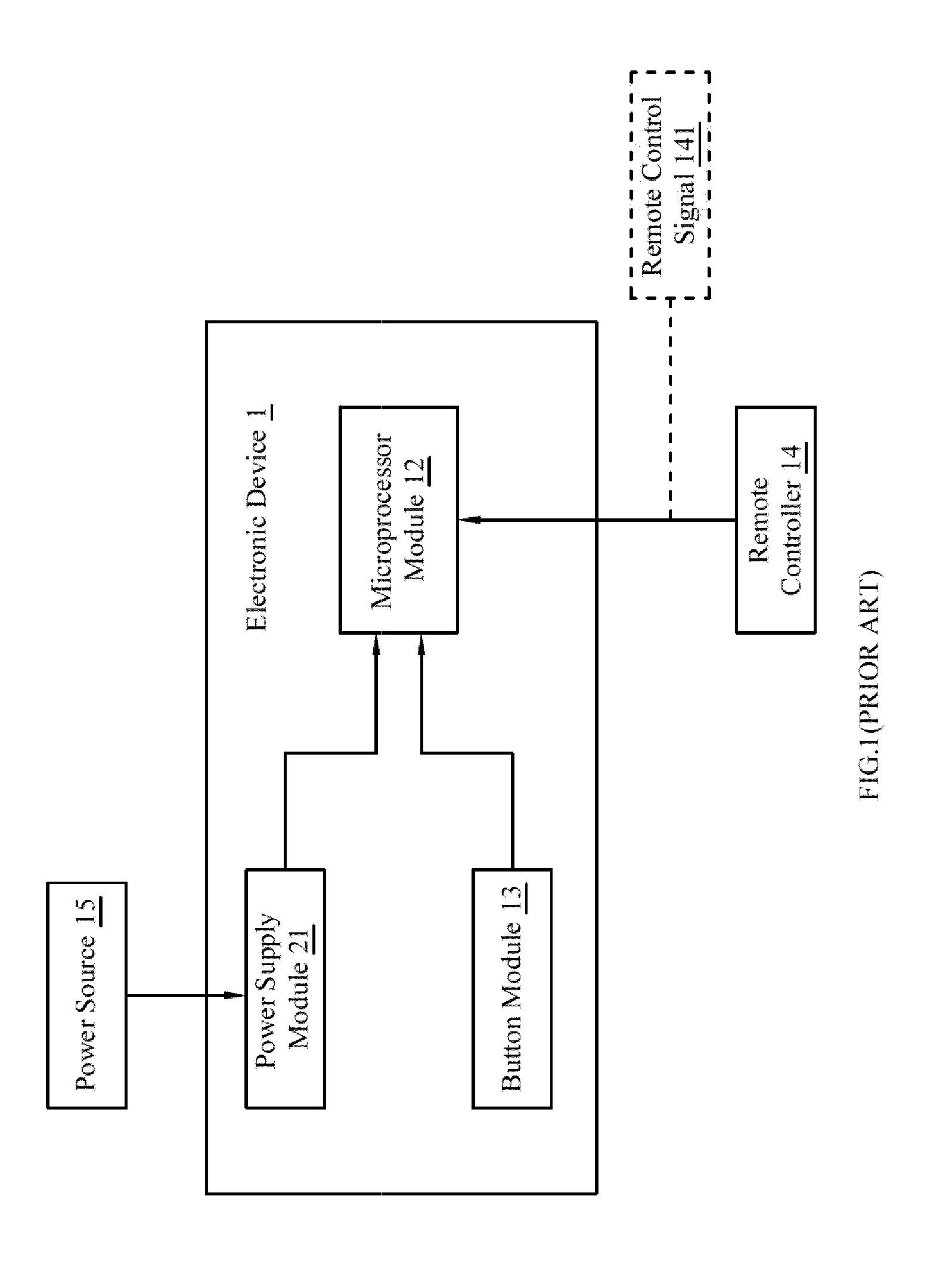
BACKGROUND OF THE INVENTION[0001]1. Field of the Invention[0002]The present invention relates to an energy-saving system for electronic apparatus: in particular, the present invention relates to an energy-saving system for electronic apparatus which allows an electronic device to consume only about 0.1 Watts (W) of electrical energy in standby mode.[0003]2. Description of Related Art[0004]Refer first to FIG. 1, wherein a block diagram for a prior art electronic apparatus is shown. The electronic apparatus comprises an electronic device 1 and a remote controller 14. The electronic device includes a power supply module 11, a microprocessor module 12 and a button module 13.[0005]The power supply module 11 is electrically connected to a power source 15. The microprocessor module 12 is electrically connected to the power supply module 11, and initiates the electronic system through the electrical energy supplied by the power supply module 11 to the microprocessor module 12. The button mo...

Claims


Application Information

Patent Timeline
IPC IPC(8): G06F1/32G06F1/00
CPCY02B60/32G06F1/3287Y02B60/1278Y02B60/1282G06F1/3203Y02D10/00Y02D30/50
Inventor HUANG, CHIEN-PANG
Owner MATRIXVIXION TECH
Learn More