Microfluidic device and method of loading sample into the microfluidic device

a microfluidic device and microfluidic technology, applied in the direction of specific gravity measurement, laboratory glassware, instruments, etc., can solve the problems of errors in inspection, manual work and various equipment, and difficulty for even a skilled medical technician to perform some inspections simultaneously

Active Publication Date: 2010-03-04
PRECISIONBIOSENSOR INC
View PDF13 Cites 26 Cited by
  • Summary
  • Abstract
  • Description
  • Claims
  • Application Information

AI Technical Summary

Problems solved by technology

Related inspection methods require a lot of manual work and various equipment.
These manual operations lead to errors in inspection results.
However, it is difficult for even a skilled medical technician to perform some inspections simultaneously.
Even in related medical pathological inspections, large and expensive automation equipment is used, and a relatively large amount of inspection materials such as blood, etc. is required.
In addition, it takes a long time to perform medical pathological inspections.
One or more embodiments include a microfluidic device which does not allow a sample treated in a sample chamber to leak through a loading hole.

Method used


Image

  • Microfluidic device and method of loading sample into the microfluidic device
  • Microfluidic device and method of loading sample into the microfluidic device
  • Microfluidic device and method of loading sample into the microfluidic device

Examples


Embodiment Construction

[0038]Reference will now be made in detail to embodiments, examples of which are illustrated in the accompanying drawings, wherein like reference numerals refer to the like elements throughout. In this regard, the present embodiments may have different forms and should not be construed as being limited to the descriptions set forth herein. Accordingly, the embodiments are merely described below, by referring to the figures, to explain aspects of the present description.

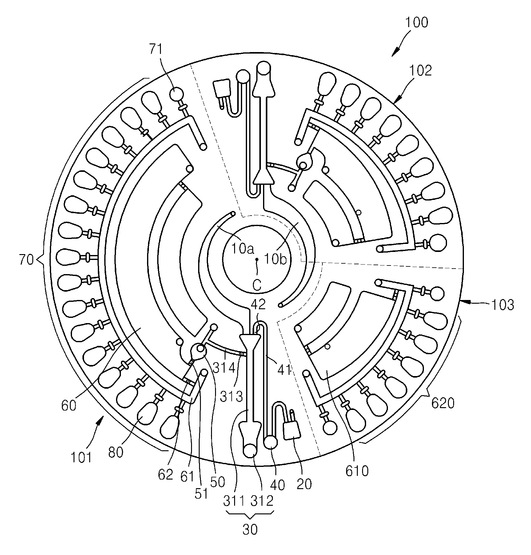
[0039]FIG. 1 illustrates a microfluidic device according to an embodiment. Referring to FIG. 1, the microfluidic device according to the present embodiment includes a rotatable (for example, a disc-shaped) platform 100 and microfluidic structures which provide a space in which fluid can be accommodated and a flow path through which fluid flows to the platform 100. The platform 100 may be rotated around the center C thereof. The microfluidic device may be mounted at a rotation driving portion (510 of FIG. 8) of an anal...


PUM

PropertyMeasurementUnit
widthaaaaaaaaaa
depthaaaaaaaaaa
diameteraaaaaaaaaa

Abstract

Provided is a microfluidic device. The microfluidic device includes a sample chamber in which a sample is accommodated. The sample chamber includes: an introduction portion including a loading hole through which the sample is loaded; an accommodation portion including a discharge hole; and a neck portion forming a boundary between the introduction portion and the accommodation portion. The neck portion provides a capillary pressure for controlling flow of the sample between the introduction portion and the accommodation portion.

Description

CROSS-REFERENCE TO RELATED APPLICATION[0001]This application claims the benefit of Korean Patent Application No. 10-2008-0086290, filed on Sep. 2, 2008, in the Korean Intellectual Property Office, the disclosure of which is incorporated herein in their entirety by reference.BACKGROUND[0002]1. Field[0003]One or more embodiments relate to a microfluidic device having a microfluidic structure and a method of loading a sample into the microfluidic device.[0004]2. Description of the Related Art[0005]Various methods of analyzing samples have been developed in a variety of application fields, such as environmental monitoring, food inspection, medical diagnostics, etc. Related inspection methods require a lot of manual work and various equipment. In order to perform inspection by using a predetermined protocol, a skilled practitioner may manually perform various operations, such as loading of samples several times, mixture, separation and movement, reaction, centrifugal separation, etc. The...

Claims


Application Information

Patent Timeline
Patent Type & Authority Applications(United States)
IPC IPC(8): G01N1/00
CPCG01N35/00029G01N2035/00495G01N2035/00039Y10T137/206Y10T137/2224G01N33/10G01N33/50G01N35/00G01N37/00
Inventor LEE, BEOM-SEOK
Owner PRECISIONBIOSENSOR INC
Why Eureka
Try Eureka