Capillary force actuator device and related method of applications

a technology of capillary force and actuator, applied in the field of capillary force actuator, can solve the problems of device becoming prone to side instability, device suffering from limitations of its own, and the inability to achieve large forces and large strokes at the same time, so as to achieve the effect of dramatic increase in the force creation of a traditional electrostatic actuator

Active Publication Date: 2012-05-15
UNIV OF VIRGINIA ALUMNI PATENTS FOUND
View PDF22 Cites 29 Cited by
  • Summary
  • Abstract
  • Description
  • Claims
  • Application Information

AI Technical Summary

Benefits of technology

[0011]An aspect of various embodiments of the present invention device and methods, which will be referred to as a Capillary Force Actuator (CFA), employs a conducting liquid bridge between two (or more) surfaces, at least one of which contains dielectric-covered electrodes. An electrical potential is applied across the electrodes. The capillary force acting upon the surfaces is modified by the applied potential. The force produced by the electrical potential acts in addition to any surface tension or (perhaps repulsive) capillary forces produced by the liquid bridge in absence of the electrical potential. This design enables the force creation of a traditional electrostatic actuator to be dramatically increased by the forces enabled by electrowetting-on-dielectric. An aspect of the various embodiments of the present invention provides, among other things, a new means to apply forces to stationary structures, to flexible elements such as membranes, to flexibly-supported elements, or to freestanding bodies.
[0014]An aspect of an embodiment of the present invention provides a method of force actuating. The method comprising: providing a the first substrate; providing an electrode layer disposed on the first substrate; providing a dielectric layer disposed on the electrode layer on the side farthest from the first substrate; providing a conducting liquid in communication with the dielectric layer of the first substrate; integrating the first substrate and the conducting liquid into a system, wherein the conducting liquid is in communication with the surface of the system, and applying an electric potential to reduce the capillary pressure within the conducting liquid with the application of sufficient electrical potential that exerts a pulling force on the first substrate thereby reducing the distance between the first substrate and the surface of the system.
[0015]An aspect of an embodiment of the present invention provides a method of force actuating. The method comprising: providing a the first substrate; providing an electrode layer disposed on the first substrate; providing a dielectric layer disposed on the electrode layer on the side farthest from the first substrate; providing a the second substrate; providing a conducting liquid in communication with the dielectric layer of the first substrate and the second substrate; and applying an electric potential to reduce the capillary pressure within the conducting liquid with the application of sufficient electrical potential that exerts a pulling force on the first and second substrates thereby reducing the distance between the first substrate and the second substrate to provide actuation.
[0016]An aspect of an embodiment of the present invention provides a method of capillary actuating. The method comprising: providing a the first substrate; providing an electrode layer disposed on the first substrate; providing a dielectric layer disposed on the electrode layer on the side farthest from the first substrate; providing a the second substrate; providing an electrode layer disposed on the second substrate; providing a dielectric layer disposed on the electrode layer on the side farthest from the second substrate; providing a conducting liquid in communication with the dielectric layer of the first substrate and the dielectric layer of the second substrate; and applying an electric potential to reduce the capillary pressure within the conducting liquid with the application of sufficient electrical potential that exerts a pulling force on the first and second substrates thereby reducing the distance between the first substrate and the second substrate to provide actuation.

Problems solved by technology

One problem with this type of actuator is that the actuation stroke depends on the thickness of the dielectric (the air gap) while actuation force is dependent on it inversely.
Thus, large forces and large strokes cannot be simultaneously achieved.
But this arrangement suffers from limitations of its own.
As the force produced by electrostatic comb actuators is increased by decreasing comb teeth spacing or increasing the length of the teeth, the device becomes prone to side instability (i.e., instability perpendicular to comb teeth and desired stroke).
In addition, practical limits of lithography also limit the teeth spacing and hence, force capability.
A main problem with the prior art uses of electrowetting for actuation is, but not limited thereto, that it is of limited application.
Specifically, it is limited to applications that rely only on the change in shape or the change in position of the liquid.
The prior art fails to provide a means to produce and sustain significant force or pressure with continuous applied voltage.
The prior art fails to leverage the fact that at small scale (for example, less than 1 millimeter), the forces of capillary pressure and surface tension can be very large, making this actuation scheme particularly appealing for micro-electromechanical systems (MEMs) and bio-MEMS, as well as for larger mesoscale (for example, approximately 1 mm) devices.

Method used


Image

  • Capillary force actuator device and related method of applications
  • Capillary force actuator device and related method of applications
  • Capillary force actuator device and related method of applications

Examples


Embodiment Construction

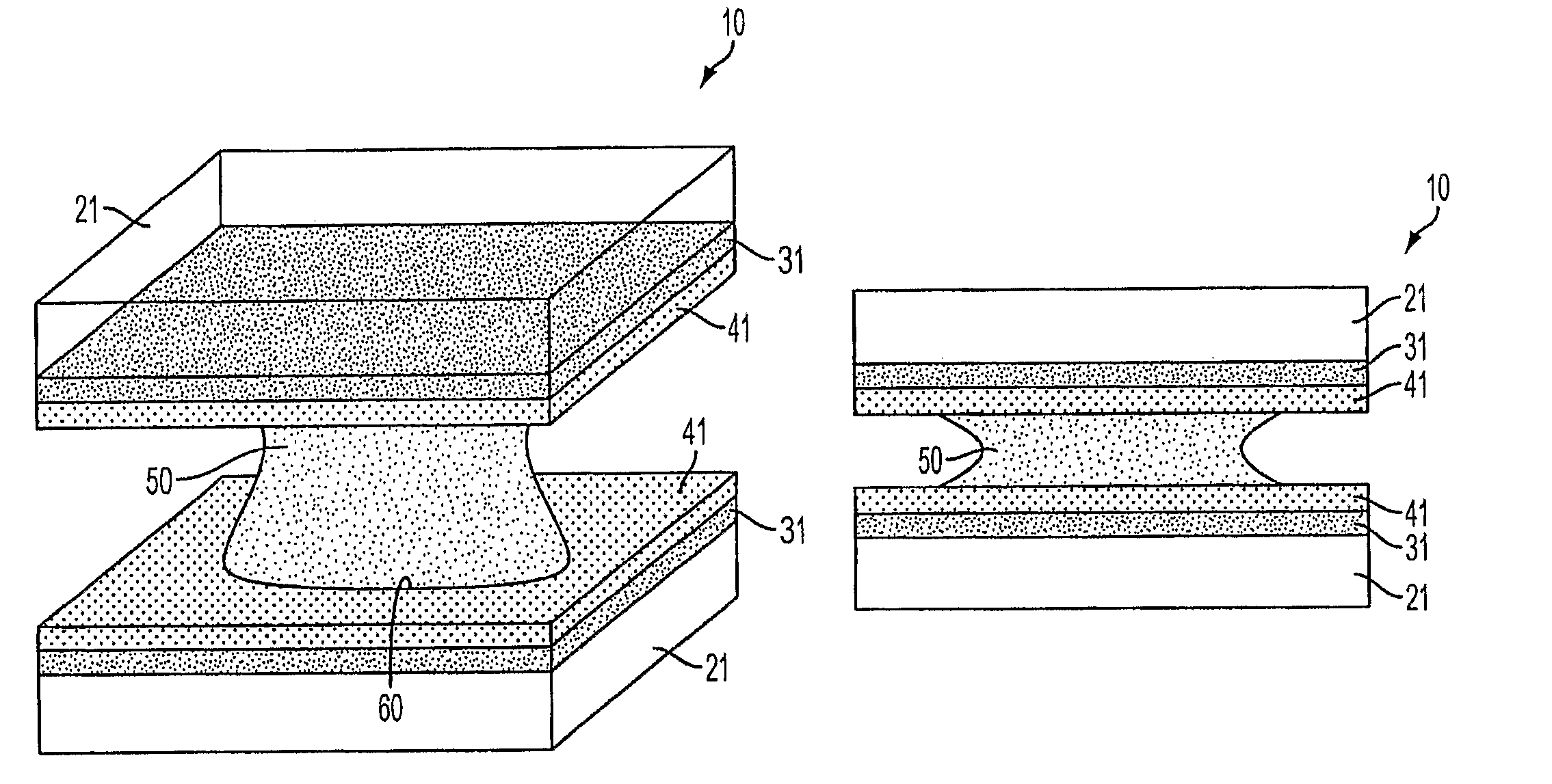
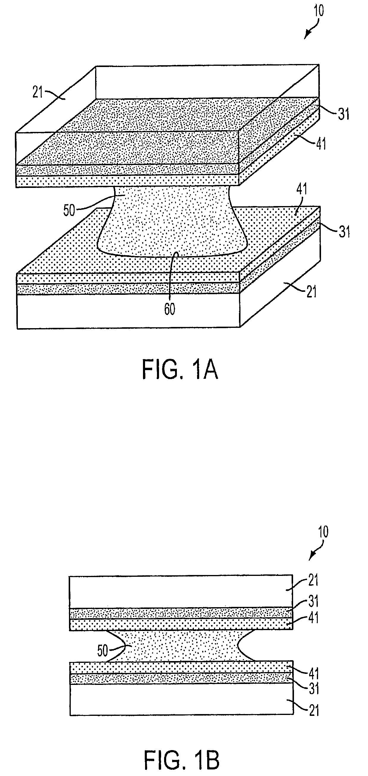
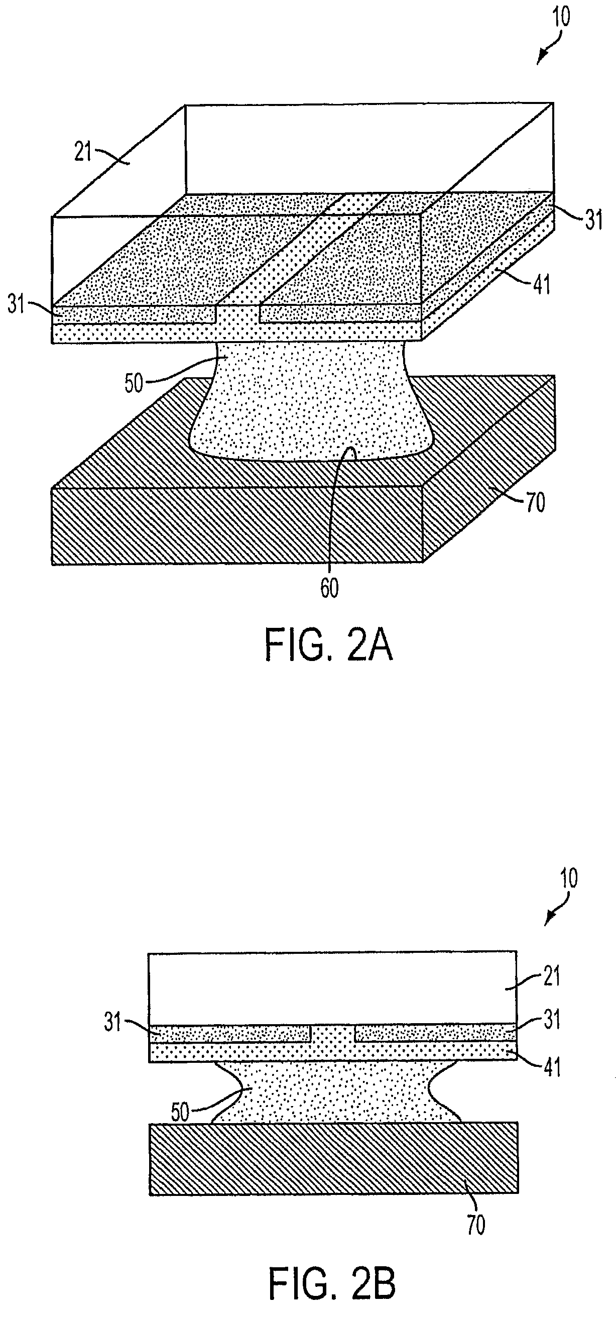
[0033]A Capillary Force Actuator (CFA) consists of at least two surfaces with a conducting liquid bridge spanning the gap between them, this bridge surrounded by an insulating non-working fluid, either liquid or gas. At least one of these surfaces contains one or more electrodes covered with a thin layer of solid dielectric material. The same or another surface contains another electrode, which may or may not be covered with a dielectric material. When an electrical potential is applied across the electrodes, the phenomenon of electrowetting occurs, especially on the dielectric-covered surface, where the contact angle of the liquid on the surface is reduced. The decrease in contact angle on the surfaces results in a change in the shape of the liquid bridge and hence in its capillary pressure. A net force is then generated by both the capillary pressure acting on the surfaces and by the surface tension forces acting at the contact line, the former typically being the predominant cont...


PUM


Abstract

An actuator capable of generates force by leveraging the changes in capillary pressure and surface tension that result from the application of an electrical potential. The device, which will be referred to as a Capillary Force Actuator (CFA), and related methods, employs a conducting liquid bridge between two (or more) surfaces, at least one of which contains dielectric-covered electrodes, and operates according to the principles of electro wetting on dielectric.

Description

RELATED APPLICATIONS[0001]The present application is a national stage filing of International Application No. PCT / US2007 / 013366, Jun. 6, 2007, which claims benefit of priority under 35 U.S.C. §119(e) from U.S. Provisional Application Ser. No. 60 / 811,169 filed Jun. 6, 2006, entitled “Method and System for Capillary Force Actuators,” of which the disclosure hereby incorporated by reference herein in entirety.FIELD OF THE INVENTION[0002]The present invention relates to the field of actuators used to create force or pressure in systems like micro-electromechanical systems (MEMS). More specifically, the present invention relates to an actuator that is driven by induced changes in the capillary pressure of a liquid through the application of an electrical potential.BACKGROUND OF THE INVENTION[0003]For micro-electromechanical systems (MEMS) and bio-MEMS (e.g., micro total analysis systems, or μTAS), a variety of force actuation methods have been used to either move structures or to induce ...

Claims


Application Information

Patent Timeline
Patent Type & Authority Patents(United States)
IPC IPC(8): H01H51/22
CPCB81B3/0021F16K99/0001F16K99/0042G02B26/004H02N11/006B01L3/5027
Inventor KNOSPE, CARL R.
Owner UNIV OF VIRGINIA ALUMNI PATENTS FOUND
Why Eureka
Try Eureka