Heat pipe with wick structure of screen mesh

a technology of heat pipe and wick, which is applied in the direction of indirect heat exchangers, lighting and heating apparatus, etc., can solve the problems of reducing the speed of condensed working fluid, limiting the heat transfer performance of heat pipes, and not always the best way to choose screen meshes with small pores, etc., to reduce the flow resistance of condensed fluid and large capillary pressure

Inactive Publication Date: 2006-08-03
HON HAI PRECISION IND CO LTD
View PDF8 Cites 30 Cited by
  • Summary
  • Abstract
  • Description
  • Claims
  • Application Information

AI Technical Summary

Benefits of technology

[0008] According to a preferred embodiment of the present invention, a heat pipe comprises a hollow pipe body for receiving a working fluid therein and a screen mesh disposed in the pipe body. The screen mesh comprises at least two layers. One of the two layers is in the form of a planar layer and the other of the two layers is in the form of a wave layer. The wave layer forms a plurality of flowing channels for the working fluid to flow from a condensing section to an evaporating section of the heat pipe. The channels formed by the wave layer of the screen mesh is capable of reducing the flow resistance to the condensed fluid to flow back while pores in the screen mesh are capable of providing a relatively large capillary pressure for drawing the condensed fluid to flow back.

Problems solved by technology

However, it is not always the best way to choose a screen mesh having small-sized pores, because the flow resistance to the condensed working fluid also increases due to a decrease in the pore size of the screen mesh.
The increased flow resistance reduces the speed of the condensed working fluid in returning back to the evaporating section and therefore limits the heat transfer performance of the heat pipe.
As a result, a heat pipe with a screen mesh that has too large or too small a pore size often suffers dry-out problem at the evaporating section as the condensed working fluid cannot be timely sent back to the evaporating section of the heat pipe.

Method used


Image

  • Heat pipe with wick structure of screen mesh
  • Heat pipe with wick structure of screen mesh
  • Heat pipe with wick structure of screen mesh

Examples


Embodiment Construction

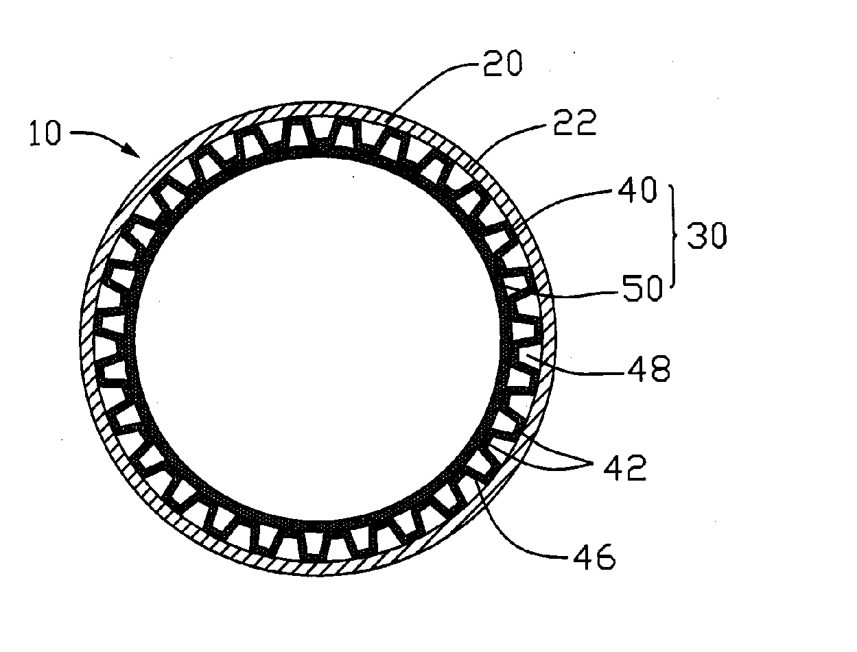
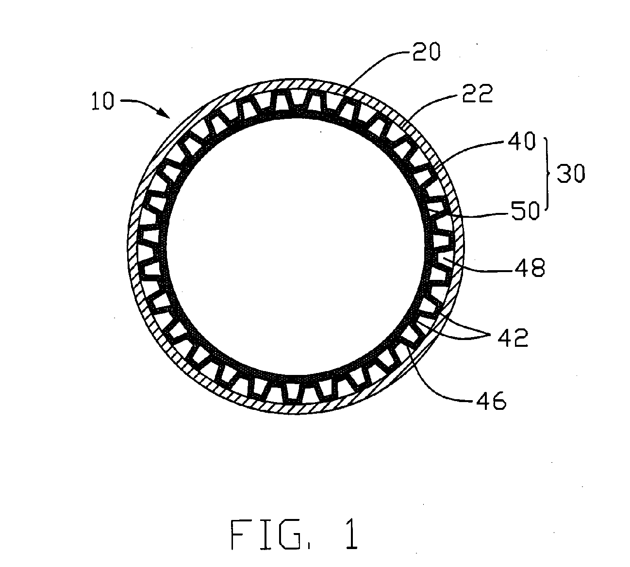
[0020] Referring to FIG. 1, a heat pipe 10 according to a preferred embodiment of the present invention comprises a hollow pipe body 20 and a screen mesh 30 disposed on an inner wall 22 of the pipe body 20. The heat pipe 10 comprises an evaporating section and a condensing section at respective opposite ends thereof, and an adiabatic section located between the evaporating section and the condensing section. The heat pipe 10 is vacuumed and two ends of the heat pipe 10 are sealed.

[0021] The pipe body 20 is made of high heat conductivity material such as copper or copper alloys. The screen mesh 30 has a plurality of pores and is saturated with a working fluid (not shown). The working fluid may be water, alcohol or other material having a low boiling point; thus, the working fluid can easily evaporate to vapor during operation when the evaporating section receives heat from a heat-generating electronic device, such as a CPU.

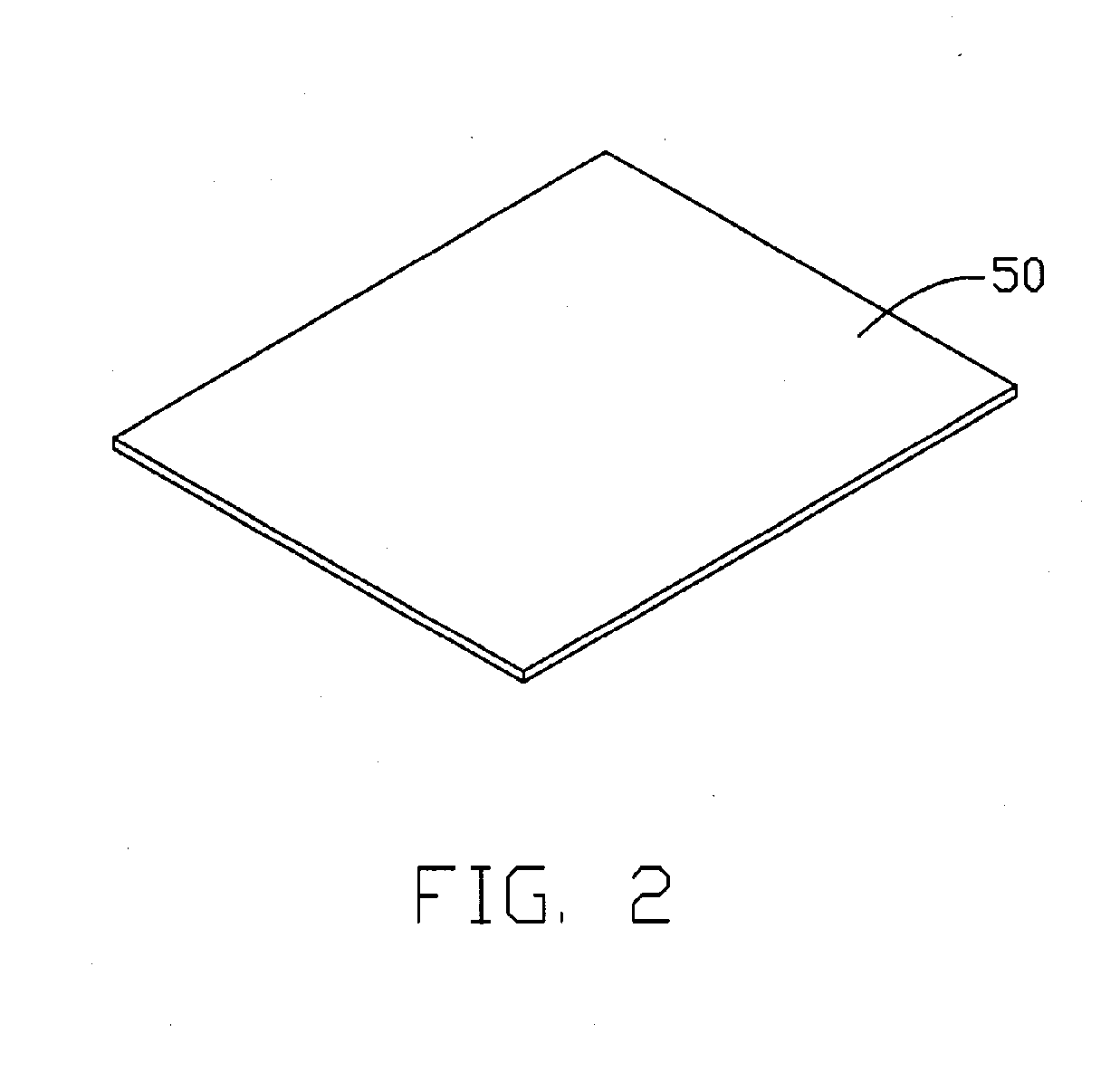
[0022] The screen mesh 30 comprises a wave layer 40 and a p...


PUM


Abstract

A heat pipe (10) includes a hollow pipe body (20) for receiving a working fluid therein and a screen mesh (30) disposed in the pipe body. The screen mesh includes at least two layers. One of the two layers is in the form of a planar layer (50) and the other is in the form of a wave layer (40). A plurality of flowing channels (48) is formed by the wave layer. The channels formed by the wave layer of the screen mesh are capable of reducing the flow resistance for the condensed fluid to flow back while pores in the screen mesh provide a relatively large capillary pressure for drawing the condensed fluid to flow back.

Description

FIELD OF THE INVENTION [0001] The present invention relates generally to heat pipes, and more particularly to a heat pipe with a wick structure of screen mesh. Description of Related Art [0002] As electronic industry continues to advance, electronic components such as central processing units (CPUs), are made to provide faster operational speeds and greater functional capabilities. When a CPU operates at a high speed, its temperature frequently increases greatly. It is desirable to dissipate the heat generated by the CPU quickly. [0003] To solve this problem of heat generated by the CPU, a cooling device is often used to be mounted on top of the CPU to dissipate heat generated thereby. It is well known that heat absorbed by fluid having a phase change is ten times more than that the fluid does not have a phase change; thus, the heat transfer efficiency by phase change of fluid is better than other mechanisms, such as heat conduction or heat convection. Accordingly, a heat pipe has b...

Claims


Application Information

Patent Timeline
Patent Type & Authority Applications(United States)
IPC IPC(8): F28D15/02
CPCF28D15/046
Inventor HONG, CHU-WANCHENG, CHING-TAILO, CHANG-TINGWU, JUNG-YUAN
Owner HON HAI PRECISION IND CO LTD
Why Eureka
Try Eureka