Folding Wing & Locking Mechanism

a technology of locking mechanism and folding wing, which is applied in the direction of wing adjustment, wing, transportation and packaging, etc., can solve the problems of commercial undesirable manual operation of the wing folding and unfolding process, and achieve the effect of reducing the number of changes for failur

Inactive Publication Date: 2010-03-04
TERRAFUGIA
View PDF4 Cites 46 Cited by
  • Summary
  • Abstract
  • Description
  • Claims
  • Application Information

AI Technical Summary

Benefits of technology

[0017]As control surfaces such as ailerons lie on the outer wing, a method of transferring control moments must be created. In the preferred embodiment, control moments are transmitted through the wing sections using torque tubes. At the wing hinge, the torque tubes are connected using a hinge-type mechanism. The folding axis of this mechanism roughly aligns with the wing fold axis when the control surfaces is placed in a predetermined (typically neutral) position. When the wing is folded, the geometry of the mechanism prevents the rotation of the control surface essentially locking it into position. When the wing is deployed, the axis of the two torque tubes are aligned and control moments can be transmitted from one torque tube to the other. The benefits of such a mechanism are that control surface is never disconnected, thus reducing the changes for failure, and the same mechanism also locks the control surface in place when the wings are folded, thus removing the need for a secondary control surface lock.

Problems solved by technology

One of the challenges of developing a practical roadable aircraft is how to safely and securely stow the wings while operating in the road environment.
Manual operation of the wing folding and unfolding process has proven to be commercially undesirable.

Method used


Image

  • Folding Wing & Locking Mechanism
  • Folding Wing & Locking Mechanism
  • Folding Wing & Locking Mechanism

Examples


Embodiment Construction

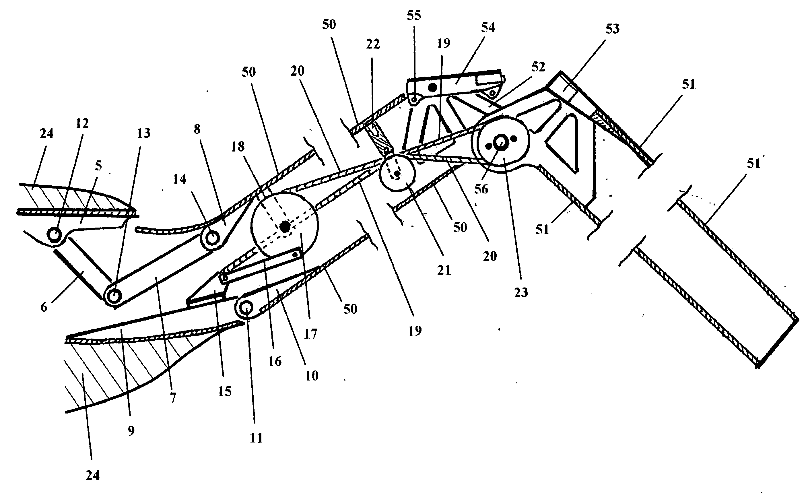
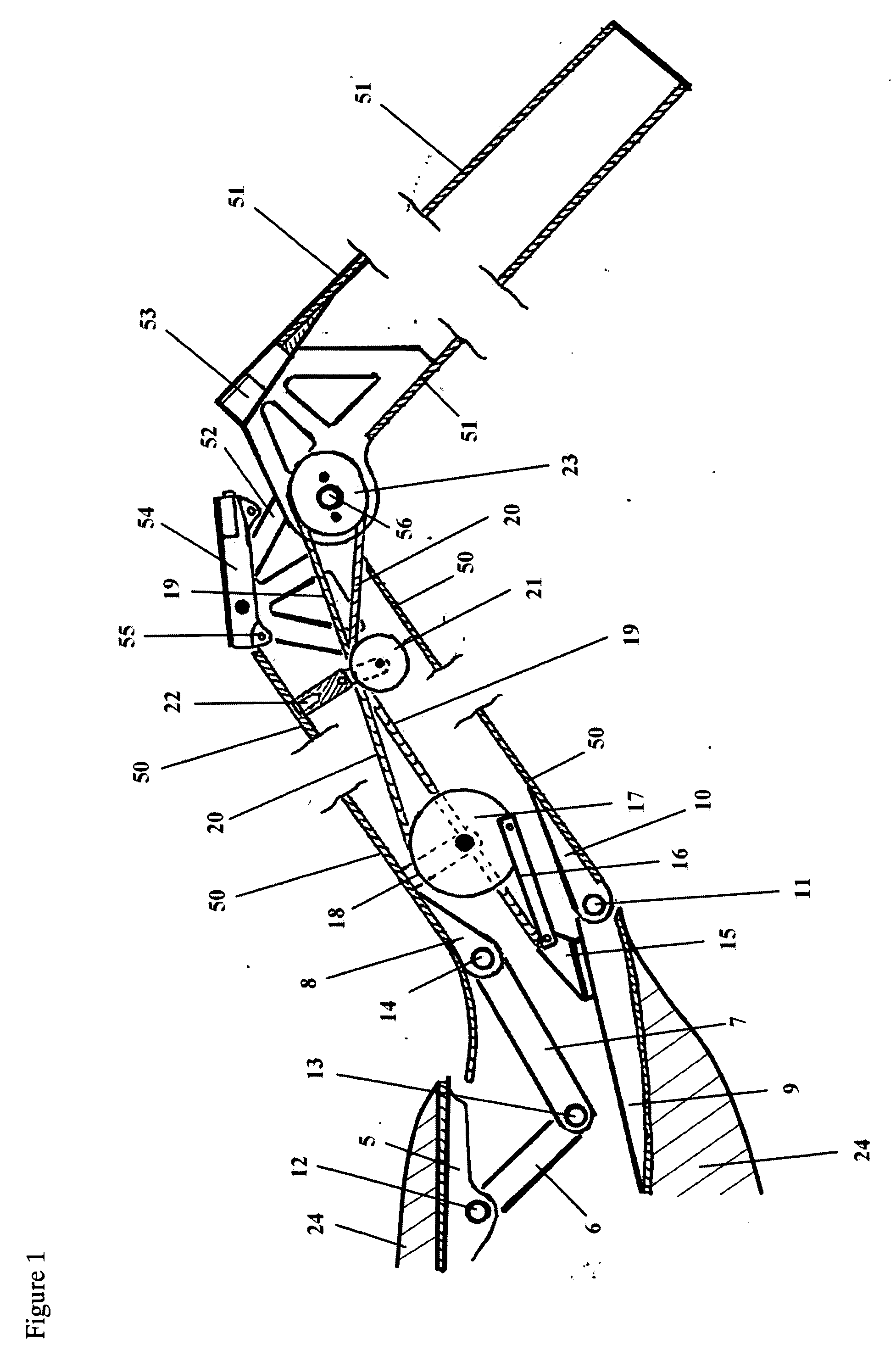
[0062]FIG. 1 shows the preferred embodiment for the cable actuation of the outer wing. The inner wing (50) is attached to the aircraft body (24), and the outer wing (51) is attached to the inner wing (50) as follows: hinge link no. 1 (5) and lower hinge base (9) are mounted in a fixed manner to the body (24). The inner wing (50) is attached to the lower hinge wing side (10) and hinge link no. 4 (8) and then pivots in relation to the body (24) via the lower hinge pin (11). The inner wing (50) is driven to rotate by the linkage comprising hinge link no. 1 (5), hinge link no. 2 (6), hinge link no. 3 (7), hinge link no. 4 (8), upper hinge pin no. 1 (12), upper hinge pin no. 2 (13) and upper hinge pin no. 3 (14). The outer wing (51) is attached to the inner wing (50) via the outer wing latch mount (53) and the inner wing latch mount (52) respectively and (53) and (52) are allowed to rotate about the mid wing pivot (56). The actuation cable system is installed in the wing mechanism as fol...


PUM


Abstract

Improved mechanisms for folding and locking an aircraft wing and controlling the wing's aileron through a wing fold have been motivated by development of a roadable aircraft. Applicable to a broader class of aircraft, these mechanisms allow for a safer, lighter-weight solution to the wing-folding challenge than currently available. The cable control system allows an outer wing section to be moved in concert with an actuated inner wing section. The locking mechanism allows for automated operation and visual inspection. The aileron control mechanism provides centering and locking in addition to flight control through the hinge axis.

Description

FEDERALLY SPONSORED RESEARCH[0001]Not ApplicableSEQUENCE LISTING OR PROGRAM[0002]Not ApplicableFIELD OF THE INVENTION[0003]This invention relates to aircraft and to roadable aircraft, a type of aircraft that can be converted into an automotive type vehicle capable of driving on the road, sometimes popularly referred to as a “flying car” or “flying-driving vehicle”. It is also relevant to applications involving hydrofoils (as distinct from airfoils).BACKGROUND OF THE INVENTION[0004]This invention, though extensible to a broader spectrum of applications, was motivated by the development of a roadable aircraft. One of the challenges of developing a practical roadable aircraft is how to safely and securely stow the wings while operating in the road environment. Conveniently stowing any aircraft's wings for storage could be accomplished with the same or similar techniques. This invention represents an improved method for accomplishing this.[0005]A common method for stowing the wings of a...

Claims


Application Information

Patent Timeline
Patent Type & Authority Applications(United States)
IPC IPC(8): B64C3/56
CPCB64C3/56
Inventor SCHWEIGHART, SAMUEL ADAMDIETRICH, CARL CURTISHEAFITZ, ANDREWZELNICK, BENJAMIN
Owner TERRAFUGIA
Why Eureka
Try Eureka