Seal assembly

a technology of sealing assembly and sealing fluid, which is applied in the direction of sealing, packaging, engine seals, etc., can solve the problems of increasing the weight and space required, affecting the sealing system between the two fluids, and requiring regular maintenan

Active Publication Date: 2010-03-04
TRELLEBORG SEALING SOLUTIONS GERMANY
View PDF32 Cites 30 Cited by
  • Summary
  • Abstract
  • Description
  • Claims
  • Application Information

AI Technical Summary

Benefits of technology

[0011]An advantage of the present invention is that it provides a sealing assembly suitable for high-temperature and high-pressure environments with bi-directional pressure.
[0012]Another advantage of the present invention is that it is suitable for aggressive application environments such as static, rotational, or reciprocating uses in combination with abrasive media.
[0013]Another advantage of the present invention is that it is suitable for oil and gas environments and other environments as well.
[0014]Yet another advantage of the present invention is that it provides a sealing assembly that includes at least two energized (particularly spring energized) seal lips able to be installed into a single groove. Pressure, potentially in the backside of a spring energized seal, can cause seal springs to collapse, but the sealing assembly of the present invention prevents such permanent deformation.
[0015]Yet another advantage of the present invention is that the system assembly is automatically self-actuating as the springs control seal lip pressures and seal system pressure relief by causing backup ring movement, or, in an alternative embodiment, seal ring movement.
[0016]Yet another advantage of the present invention is that the seal assembly is provided with various vent channels or passageways that permit the seal assembly to vent and self-clean as contaminants are removed from the vicinity of the seal assembly via transport through the vent channels.

Problems solved by technology

Sealing systems between the two fluids unfortunately require regular maintenance.
Reliability of the sealing system is of paramount concern, because of the cost of downtime in the drilling operation in the retrieval of the underground drilling head and seal.
Prior sealing systems have been susceptible to wear and degradation as contaminants, abrasive media, and debris enter the sealing area.
This has increased the weight and space required, increased the overall cost of the system, and has not provided necessary sealing performance for the expected duration due to eventual pressure build-up between the two seals eventually destroying the seals.

Method used


Image

  • Seal assembly
  • Seal assembly
  • Seal assembly

Examples


Embodiment Construction

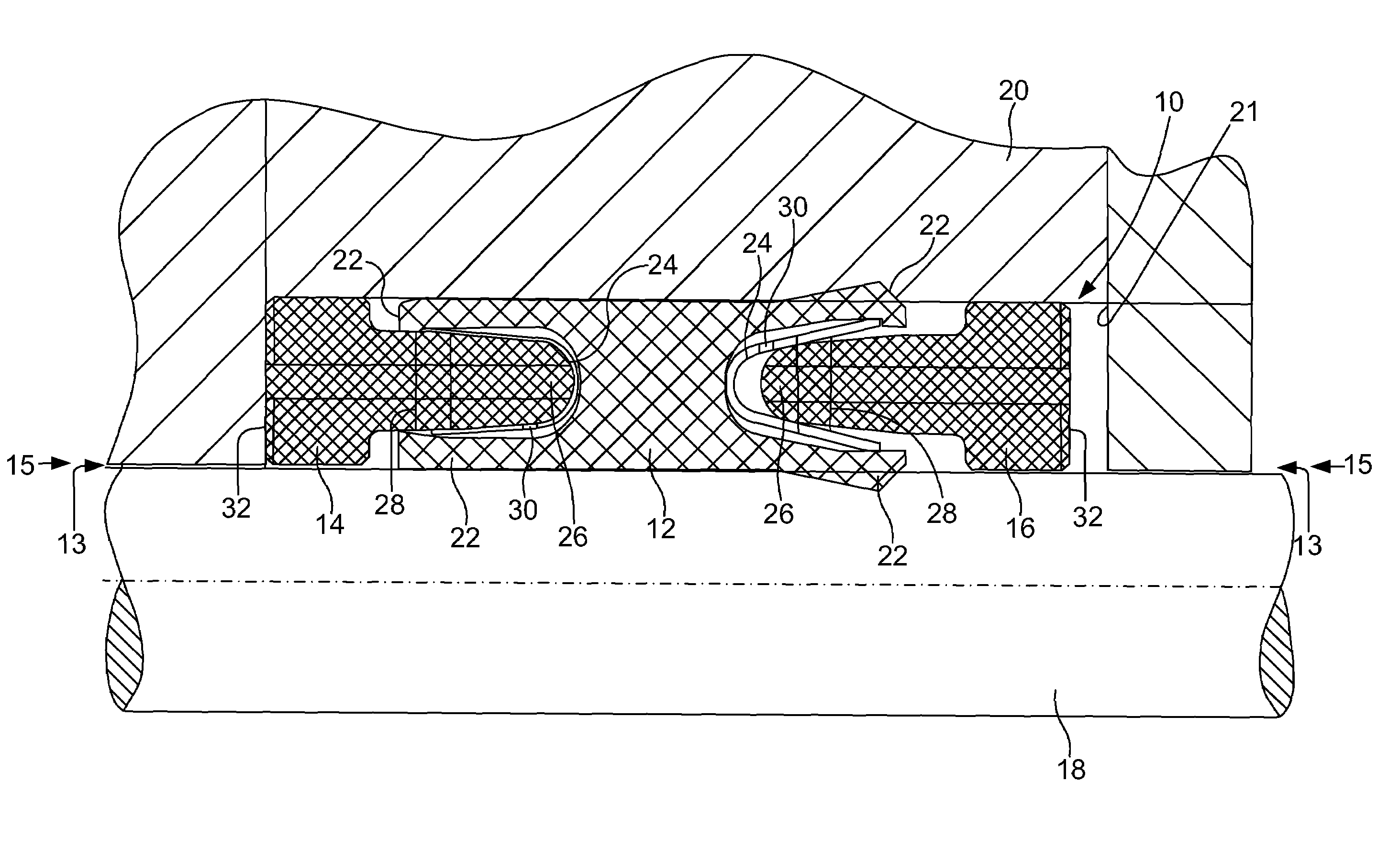
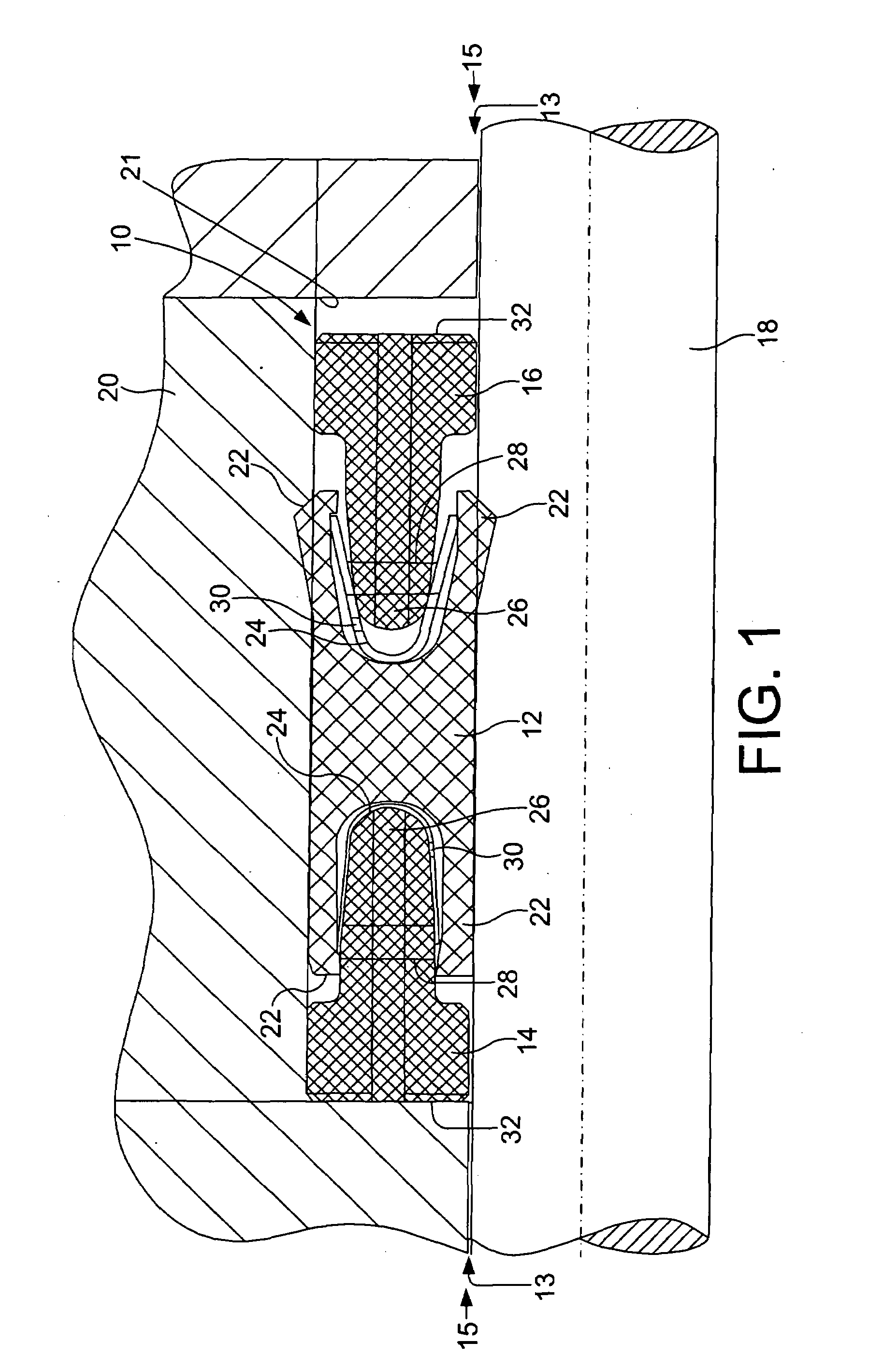
[0027]Referring now to the drawings, and more particularly to FIG. 1, there is shown an embodiment of a sealing assembly of the present invention, the sealing assembly of this embodiment labeled as 10. Sealing assembly 10 generally includes a sealing component 12, a first backup ring component 14, and a second backup ring component 16. In the fully assembled or packaged form of assembly 10, sealing component 12, ring 14, and ring 16 are disposed annularly about a shaft 18 in facing abutting relationship to one another so as to encase and interfit with sealing component 12. Rings 14 and 16 have complementary protuberance mating features 26 that form a tang, or member, that interfits with sealing component 12.

[0028]In this manner, the arrangement of rings 14 and 16 serves to prevent seal collapse of sealing component 12 between the shaft 18 and housing 20. Assembly 10 may be considered to form a kit having a collection of discrete, individual, separable pieces that can be detachably c...


PUM


Abstract

A sealing assembly for a shaft includes a sealing component, a first ring, a second ring, and at least one energizer. The first ring is annularly disposed about the shaft, the first ring having at least one first protuberance interfittable with the sealing component. The second ring is annularly disposed about the shaft in facing opposition to the first ring, the second ring having at least one second protuberance interfittable with the sealing component. The at least one energizer energizes the seal component, the at least one energizer being adjacent the at least one first protuberance or the at least one second protuberance.

Description

BACKGROUND OF THE INVENTION[0001]1. Field of the Invention[0002]The present invention relates to sealing systems, and, more particularly, to multi-piece sealing assemblies.[0003]2. Description of the Related Art[0004]Oil drilling devices typically include an arrangement or drill head that is located underground or “down hole” that is in a highly unique environment. The pressures and temperatures are typically, both high at over 15,000 psi and potential temperatures of approximately 400° F. The drill head and system utilize hydraulic fluid on one side and drilling mud (a lubricant and abrasive) on another. Sealing systems between the two fluids unfortunately require regular maintenance. Reliability of the sealing system is of paramount concern, because of the cost of downtime in the drilling operation in the retrieval of the underground drilling head and seal. Additionally, when installed the sealing systems must be able to be sealed in both directions, (e.g. there are times when eit...

Claims


Application Information

Patent Timeline
Patent Type & Authority Applications(United States)
IPC IPC(8): F16J15/32
CPCF16J15/166Y10S277/928F16J15/3236F16J15/3212
Inventor CASTLEMAN, LARRY J.JONES, GREGORY D.BOWEN, BRIAN
Owner TRELLEBORG SEALING SOLUTIONS GERMANY
Why Eureka
Try Eureka