Sensor arrangement

Active Publication Date: 2011-03-03
DELPHI TECH IP LTD
View PDF9 Cites 15 Cited by
  • Summary
  • Abstract
  • Description
  • Claims
  • Application Information

AI Technical Summary

Benefits of technology

[0008]An advantage of the invention is that the electromagnetic solenoid permits a variable magnetic field to be used to detect the ferrous target such that the magnetic field strength generated by the solenoid is adaptable to suit the environmental surroundings of the sensor arrangement. Furthermore, the Hall effect device has a rapid response time and does not suffer from significant hysteresis.
[0009]Although not essential to the invention, in order to maximise sensing accuracy the Hall effect device may be positioned to be in alignment with a longitudinal axis of the electromagnetic solenoid so that the Hall effect device is exposed to a region having the greatest intensity of magnetic field. Furthermore, although the electromagnetic solenoid and the Hall effect device may be arranged such that they are physically separate from one another, conveniently they may be combined into a single package for ease of installation.
[0010]In a preferred embodiment, the sensor arrangement includes a control system configured such that an electrical output signal provided by the Hall eff

Problems solved by technology

It is common that in a fuel injection pump the internal volume of the pump housing and, therefore, the immediate environment of the inlet metering valve is exposed to fuel which makes the positional determination of the inlet metering valve particularly troublesome.
Although there are some contactless position sensors

Method used


Image

  • Sensor arrangement
  • Sensor arrangement

Examples


Embodiment Construction

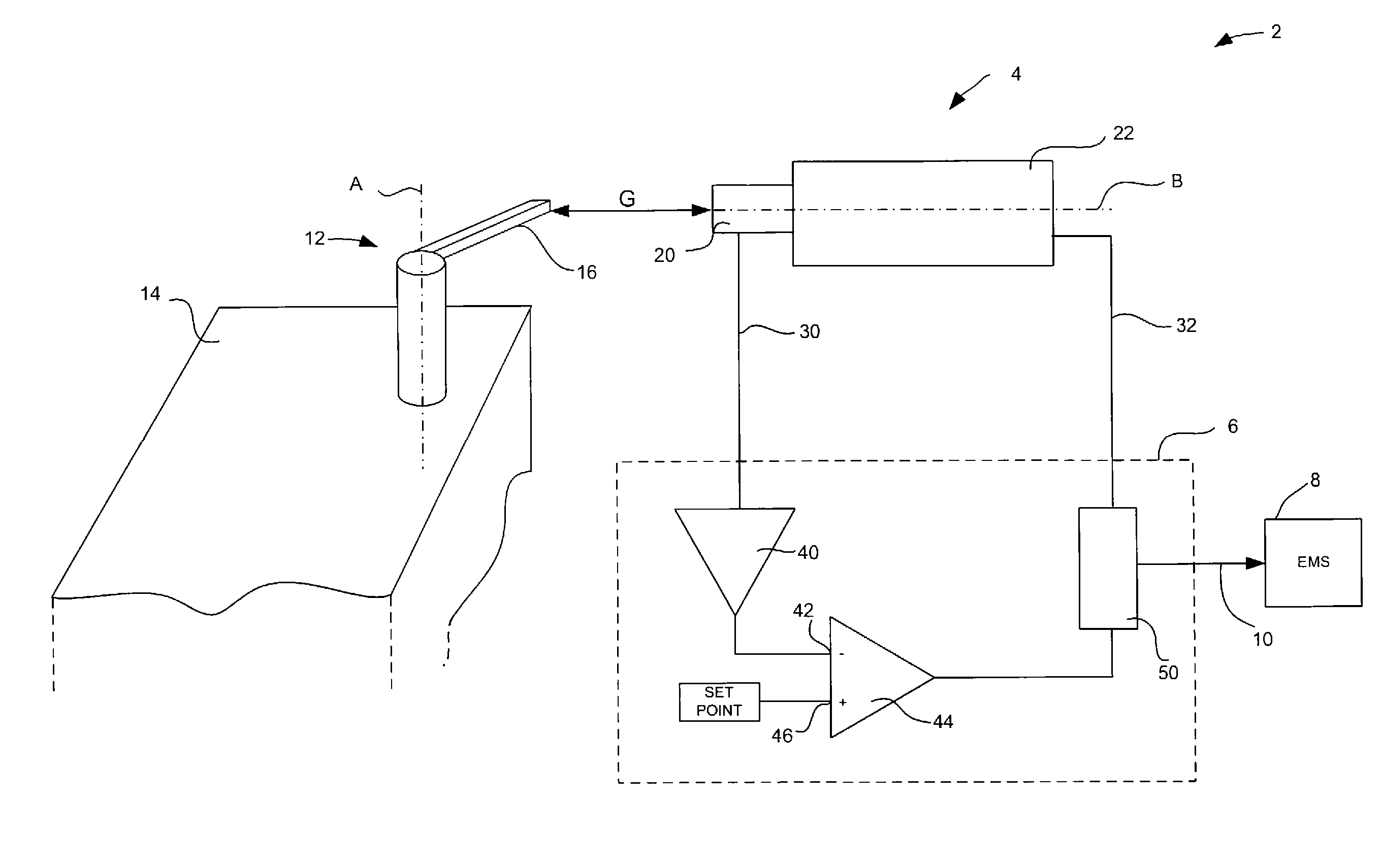
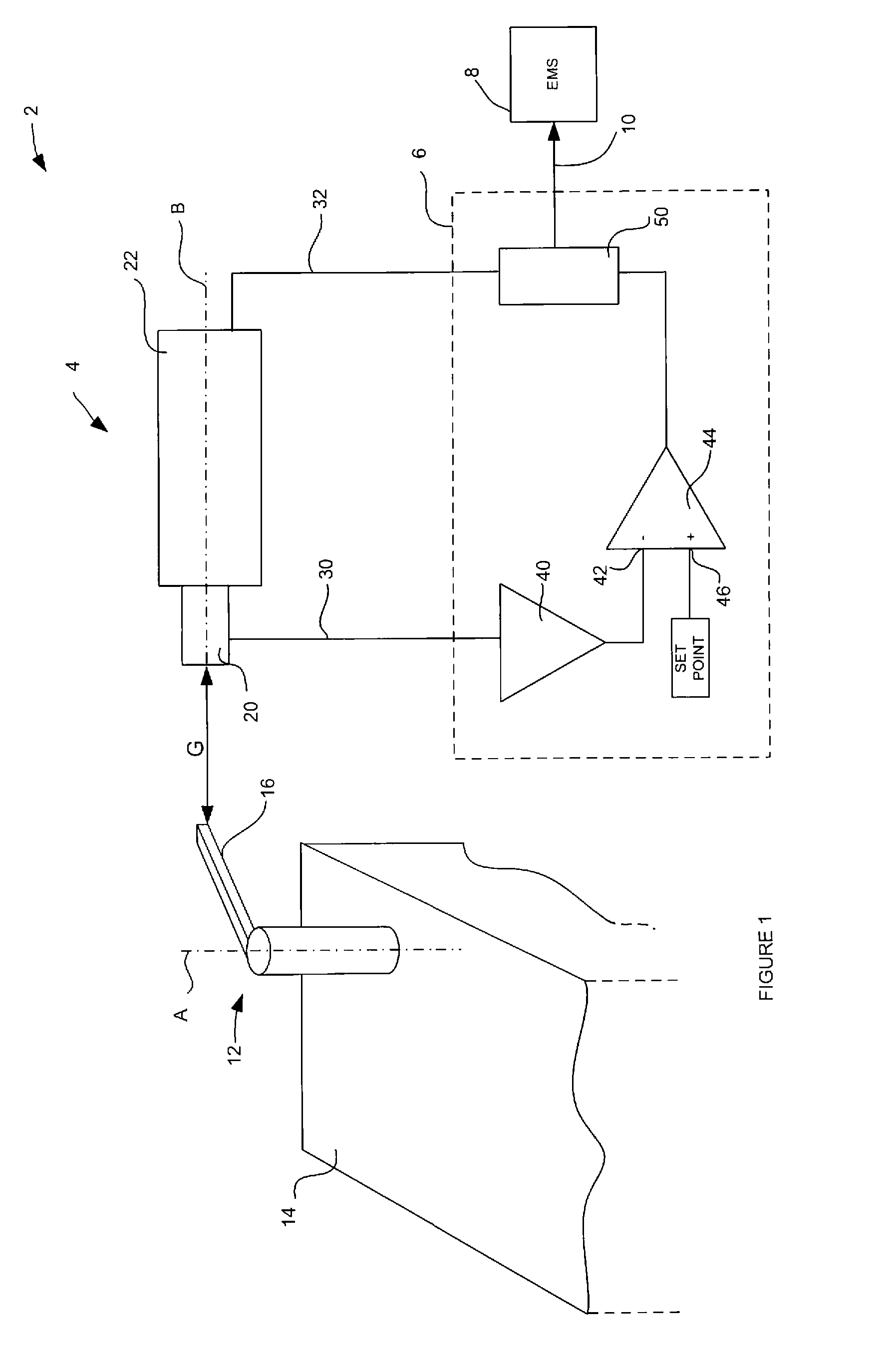
[0021]Referring to FIG. 1, a sensor arrangement 2 in accordance with the invention includes a sensor module 4 that is connected electrically to a control unit 6. Although not shown in FIG. 1, the sensor arrangement 2 forms a part of a compression-ignition internal combustion engine and, to this end, the control unit 6 is interfaced with an engine management system (EMS) 8 via a data connection 10 by which means the EMS 8 is able to gather sensor data from the sensor arrangement 2 for use in controlling the engine.

[0022]As can be seen in FIG. 1, an inlet metering valve 12 is received by a body of a distributor fuel pump 14 (only shown partially in FIG. 1) and includes a control arm 16 extending radially away from a longitudinal axis A of the inlet metering valve 12. Although not shown in FIG. 1, the control arm 16 is connected to a throttle and governor linkage of the fuel pump 14 so that the angular position of the inlet metering valve 12 is controllable in response to the level of ...


PUM


Abstract

A sensor arrangement and a method for its use for detecting the proximity of a ferrous target, the sensor arrangement comprising a sensor body including a magnetic field source and a Hall effect device, wherein the magnetic field source is an electromagnetic solenoid. The invention has particularly utility, but is not so limited, to the field of fuel injection pumps in which it is necessary to determine the volume of fuel that is delivered to the cylinders of the engine without affecting the operation of the engine.

Description

TECHNICAL FIELD[0001]The invention relates to a sensor arrangement and, more particularly, to a sensor arrangement for detecting the proximity of a ferrous ‘target’ to the sensor arrangement. The invention also relates to a specific application of a fuel injection pump of an internal combustion engine having such a sensor arrangement.SUMMARY OF THE INVENTION[0002]There are many applications in which it is required to monitor the position of an object; a so-called ‘target’. One such application is a rotary fuel injection distributor pump such as may be used on a compression-ignition internal combustion engine, otherwise known as a diesel engine.[0003]The general structural configuration of a distributor fuel pump is known in the art, for example as disclosed in the Applicant's European patent EP1356196, and includes an inlet metering valve that is angularly moveable about its axis to control the volume of fuel that is supplied to one or more pumping elements of the fuel pump. The ang...

Claims


Application Information

Patent Timeline
IPC IPC(8): G01R33/06
CPCG01D5/147F02M59/44
Inventor BOOTLE, GEOFFREY DAVIDDELLER, JOHN
Owner DELPHI TECH IP LTD
Why Eureka
Try Eureka