Non-contact power transmission device

a power transmission device and non-contact technology, applied in the direction of electric variable regulation, process and machine control, instruments, etc., can solve the problems of transmitters unintentionally providing power to a plurality of receivers, no frequency selectivity for power transmission between power transmitters,

Active Publication Date: 2010-03-04
SONY CORP
View PDF21 Cites 426 Cited by
  • Summary
  • Abstract
  • Description
  • Claims
  • Application Information

AI Technical Summary

Problems solved by technology

However, there is no frequency selectivity for power transmission between a power transmitter and a power receiver.
Therefore,

Method used


Image

  • Non-contact power transmission device
  • Non-contact power transmission device
  • Non-contact power transmission device

Examples


first embodiment

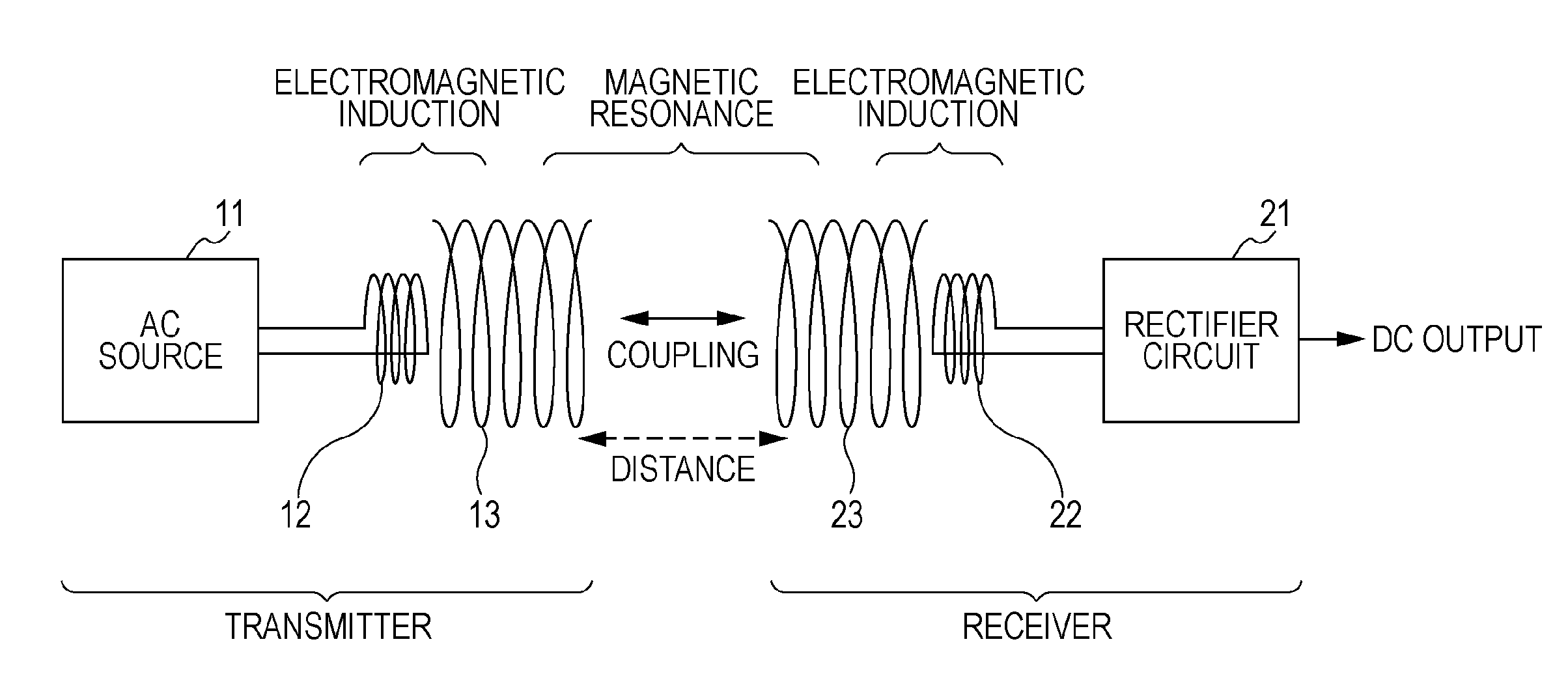
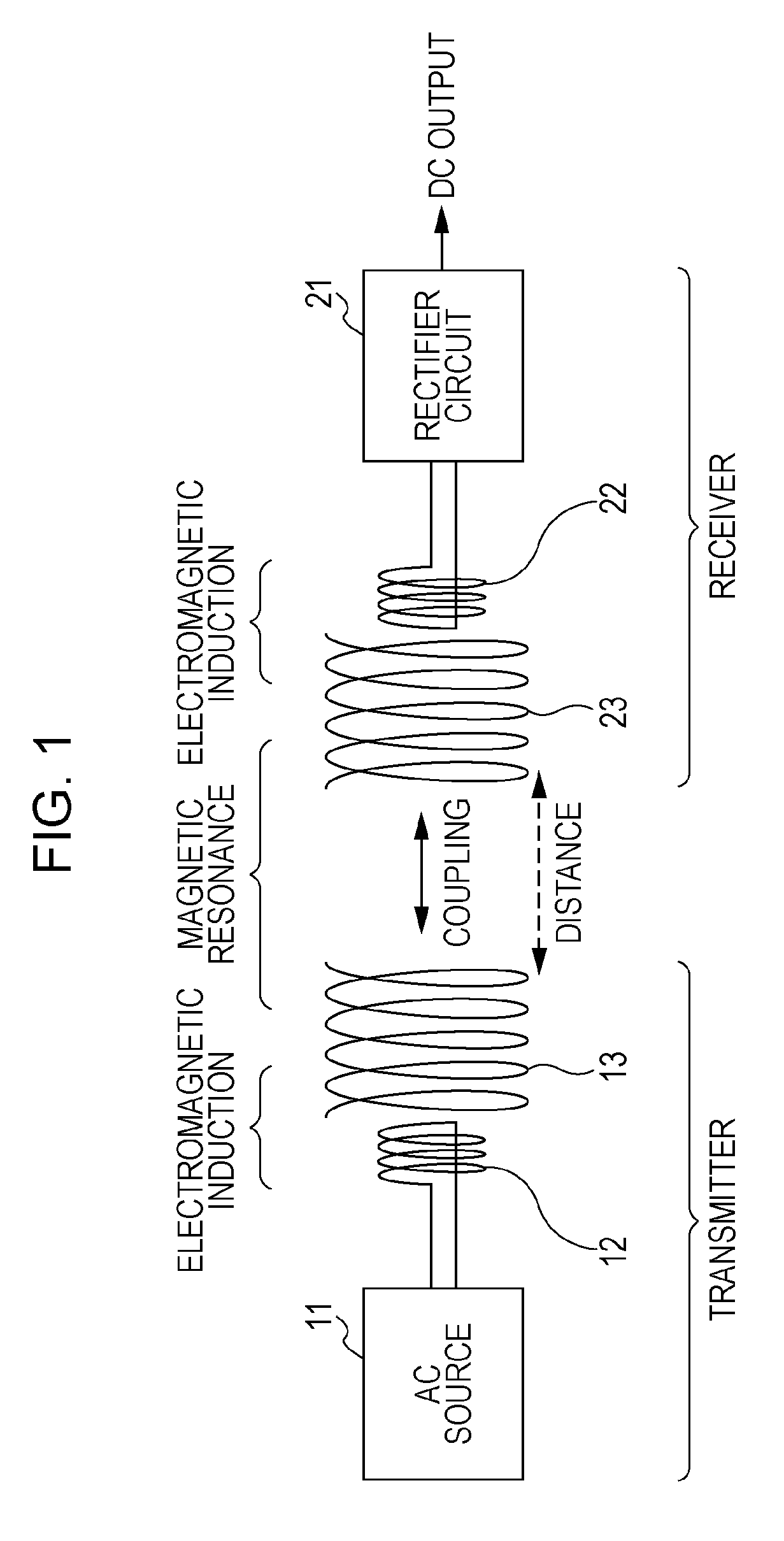
[0037]FIG. 1 illustrates a configuration of a non-contact power transmission device according to the first embodiment of the present invention. The non-contact power transmission device according to the first embodiment has a one-to-one correspondence of a transmitter and a receiver. As illustrated in FIG. 1, the transmitter has an alternating current (AC) source 11, an excitation element 12, and a resonance element 13. The receiver has a rectifier circuit 21, an excitation element 22, and a resonance element 23.

[0038]The excitation elements 12 and 22 and the resonance elements 13 and 23 are each formed of an air-core coil of a wound wire to utilize inductance. The excitation element 12 and the resonance element 13 of the transmitter are strongly coupled by electromagnetic induction. Similarly, the excitation element 22 and the resonance element 23 are strongly coupled by electromagnetic induction.

[0039]The resonance element 13 and the resonance element 23 are disposed at relative p...

second embodiment

[0046]FIG. 5 illustrates a configuration of a non-contact power transmission device according to the second embodiment of present invention. The non-contact power transmission device according to the second embodiment has one transmitter and two receivers. That is, the non-contact power transmission device has a one-to-two correspondence between the transmitter and the receivers.

[0047]The transmitter has an oscillation-frequency variable AC source 31 for applying an alternating current, an excitation element 32, and a resonance element 33 of which the resonant frequency is variable.

[0048]The oscillation-frequency variable AC source 31 is an alternating current source with variable alternating current frequency which supplies an alternating current to the excitation element 32, thereby inducing a current in the resonance element 33 by electromagnetic induction. The frequency of an alternating current generated in the oscillation-frequency variable AC source 31 can be controlled so as...

third embodiment

[0060]FIG. 9 illustrates a configuration of a non-contact power transmission device according to the third embodiment of the present invention. In the non-contact power transmission device according to the third embodiment, inductance is varied by changing the entire length of a coil by means of changing the winding pitch without changing the wire length, in order to vary the resonant frequency of the transmitter. Note that components similar to those of non-contact power transmission device of the second embodiment are designated by the same reference numerals used in the second embodiment, and thus the detailed description thereof will be omitted.

[0061]A transmitter has an oscillation-frequency variable AC source 31 for applying an alternating current, an excitation element 32, and a resonance element 35 of which the resonant frequency is variable.

[0062]The oscillation-frequency variable AC source 31 is an alternating current source with variable alternating current frequency and ...


PUM


Abstract

An electromagnetic resonance non-contact power transmission device includes a transmitter including a transmitter resonance element having a mechanism for discretely or continuously varying a resonant frequency, a transmitter excitation element coupled to the transmitter resonance element by electromagnetic induction, and an alternating current source for applying an alternating current at the same frequency as the resonant frequency to the transmitter excitation element, and a plurality of receivers each including a receiver resonance element having a specific resonant frequency, a receiver excitation element coupled to the receiver resonance element by electromagnetic induction, and an output circuit for outputting an electric current induced by the receiver excitation element. Electric power is transmitted selectively from the transmitter to any of the receivers having different specific resonant frequencies by changing the resonant frequency of the transmitter.

Description

BACKGROUND OF THE INVENTION[0001]1. Field of the Invention[0002]The present invention relates to non-contact power transmission devices for performing wireless electric power transmission.[0003]2. Description of the Related Art[0004]Recently, non-contact power supply devices which wirelessly supply electric power to apparatuses without power cables or the like have come to be in practical use. The principles upon which wireless electric power transmission is realized are generally categorized into three types: electromagnetic induction type; radio reception type; and resonance type.[0005]Electromagnetic induction non-contact power transmission employs the phenomenon in which application of an electric current to one of adjacent coils induces an electromotive force in the other coil with magnetic flux as the medium. This technique has gradually become widespread in non-contact charging of mobile terminals.[0006]In radio reception non-contact power transmission, radio wave energy is t...

Claims


Application Information

Patent Timeline
IPC IPC(8): H02J17/00H01Q7/00
CPCB60L11/182Y02T90/121B60L11/1846H01Q1/248H02J17/00H04B5/0031H04B5/0037H04B5/0093Y02T10/7005Y02T90/122Y02T90/128Y02T90/14Y02T90/163Y02T90/169Y04S30/14B60L11/1838Y02T10/7072B60L53/12B60L53/65H02J50/12H02J50/40H02J50/60B60L53/68Y02T90/12Y02T90/16Y02T90/167Y02T10/70Y04S30/12H02J50/80
Inventor MITA, HIROYUKI
Owner SONY CORP
Why Eureka
Try Eureka