Grip device and information processing unit

Active Publication Date: 2010-03-04
PANASONIC CORP
View PDF14 Cites 18 Cited by
  • Summary
  • Abstract
  • Description
  • Claims
  • Application Information

AI Technical Summary

Benefits of technology

[0014]According to the present invention, the pulling and re

Problems solved by technology

Thus, the retracting operation of the h

Method used


Image

  • Grip device and information processing unit
  • Grip device and information processing unit
  • Grip device and information processing unit

Examples


embodiment

1. Configuration of Information Processing Unit

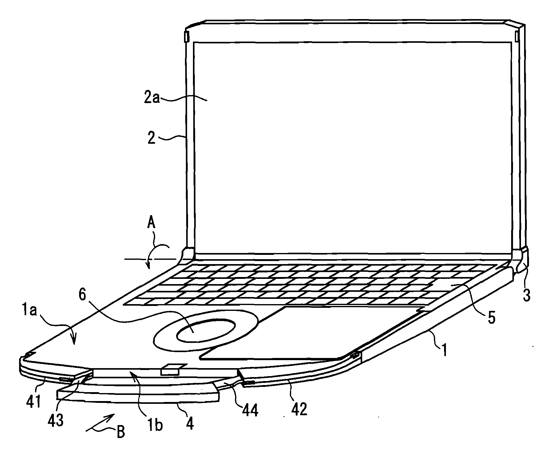
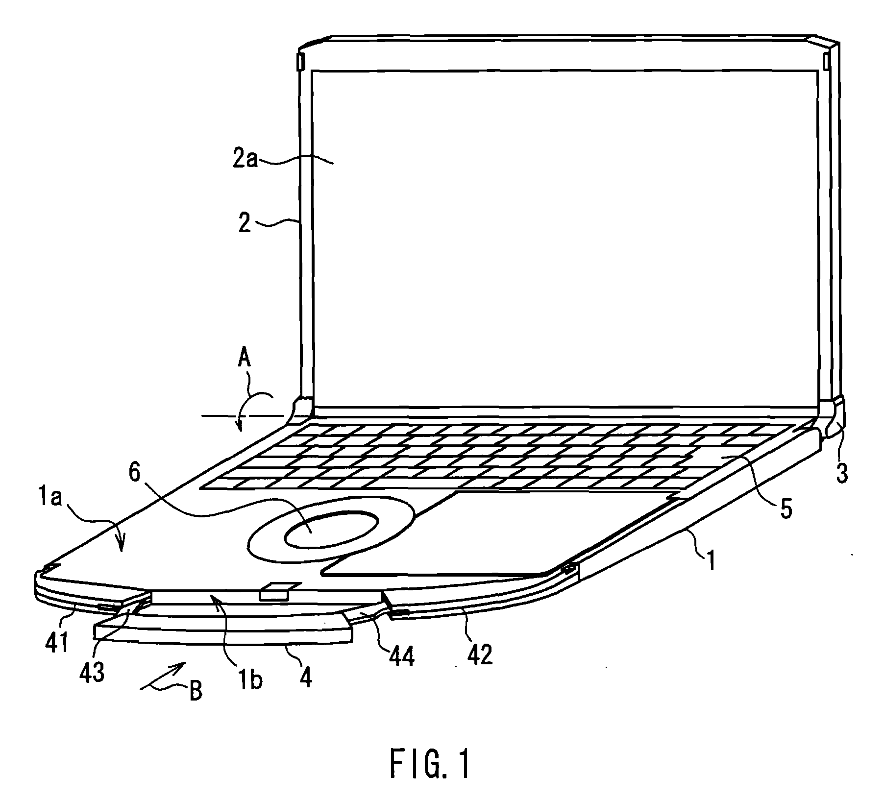
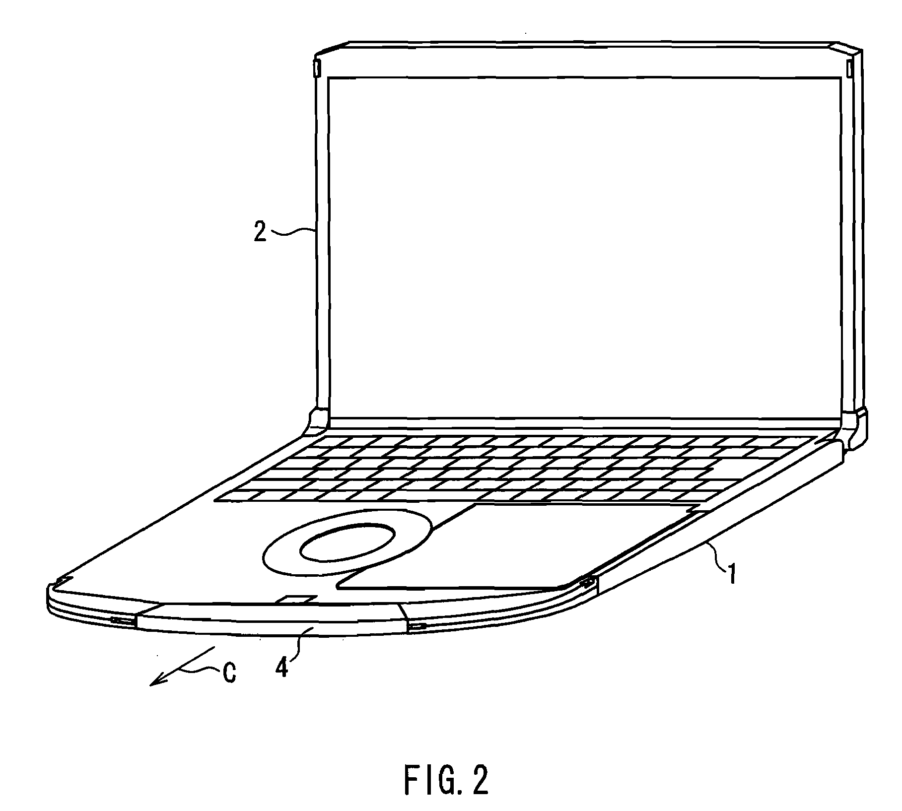
[0031]FIGS. 1 and 2 are perspective views showing the appearance of an information processing unit including a grip device of this embodiment. FIGS. 1 and 2 show a first state of a notebook computer as an example of the information processing unit. In FIG. 1, a handle is extended. Hereinafter, the state shown in FIG. 1 is referred to as an “extended state”, and the position of the handle in this state is referred to as an “extended position”. In FIG. 2, the handle is retracted. Hereinafter, the state shown in FIG. 2 is referred to as a “retracted state”, and the position of the handle in this state is referred to as a “retracted position”. FIG. 3 is a perspective view showing a second state of the notebook computer of this embodiment. In this embodiment, the notebook computer is used as an example of the information processing unit. However, the information processing unit may be any portable equipment such as a portable telephone or me...


PUM


Abstract

In a grip device of the present invention, shielding members are placed in the openings of a handle in which arm members are to be arranged, respectively. This can make it difficult for a foreign matter to enter the handle via the openings. The presence of the shielding members can prevent a foreign matter from being caught between the handle and each of the arm members when the handle is moved from the extended position to the retracted position, resulting in a smooth movement of the handle.

Description

BACKGROUND OF THE INVENTION[0001]1. Field of the Invention[0002]The present invention relates to a grip device with a handle that can be held by a user, and an information processing unit including the grip device.[0003]2. Description of Related Art[0004]A conventional notebook computer with a built-in handle has been proposed for ease of carrying. JP 6(1994)-314138 A and JP 6(1994)-309065 A disclose a grip device including arm members for connecting a grip of a handle and the main body.[0005]FIG. 7 is a perspective view of a conventional notebook computer with a handle. FIG. 8 is a plan view showing the main parts in the vicinity of the handle of the notebook computer shown in FIG. 7. The notebook computer shown in FIGS. 7 and 8 includes a first case 101 and a second case 102. The first case 101 is provided with a keyboard, an information processing means, etc. The second case 102 is provided with a liquid crystal display. The first case 101 and the second case 102 are supported ro...

Claims


Application Information

Patent Timeline
IPC IPC(8): G06F1/16B25G1/04
CPCG06F1/1616Y10T16/473G06F1/1656H05K5/023
Inventor NAGAMURA, YOSHIAKINAKATANI, HITOSHITANAKA, SHINTAROKANEKO, HARUKA
Owner PANASONIC CORP
Why Eureka
Try Eureka