Gas turbine transition duct apparatus

a technology of transition duct and gas turbine, which is applied in the direction of machines/engines, stators, liquid fuel engines, etc., can solve problems such as stress failures

Active Publication Date: 2010-03-04
SIEMENS ENERGY INC
View PDF10 Cites 54 Cited by
  • Summary
  • Abstract
  • Description
  • Claims
  • Application Information

AI Technical Summary

Problems solved by technology

The transition ducts are exposed to these high temperature gases and pulsating pressures, and vibrations can cause deflections in various locations of the tubular main bodies and collars.
Due the nature of holding a component in a dynamic flow condition with temperature gradients, stress failures may occur, for example, in corner portions of the tubular main bodies.

Method used


Image

  • Gas turbine transition duct apparatus
  • Gas turbine transition duct apparatus
  • Gas turbine transition duct apparatus

Examples


Embodiment Construction

[0024]In the following detailed description of the preferred embodiment, reference is made to the accompanying drawings that form a part hereof, and which is shown by way of illustration, and not by way of limitation, a specific preferred embodiment in which the invention may be utilized and that changes may be made without departing from the spirit and scope of the present invention.

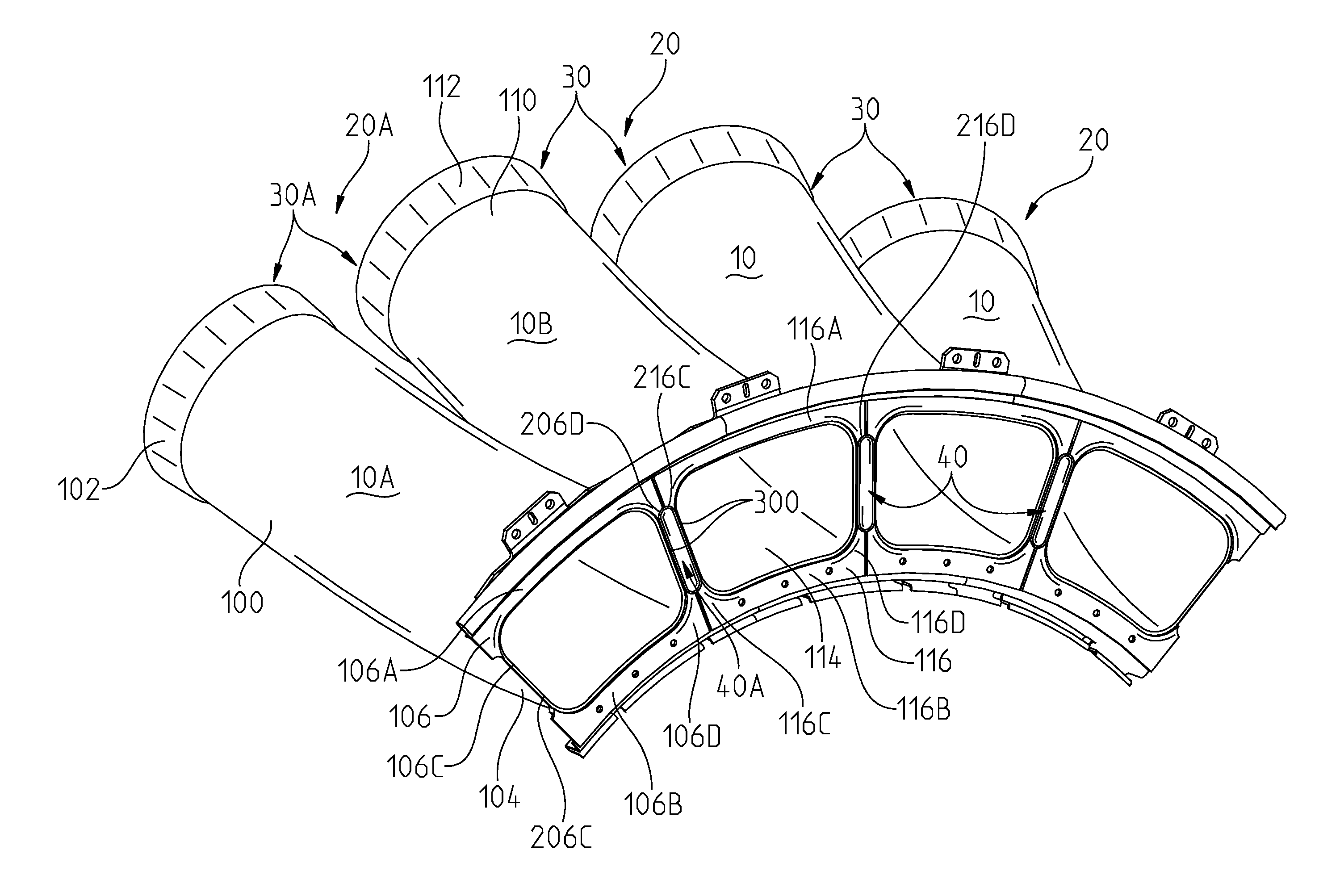
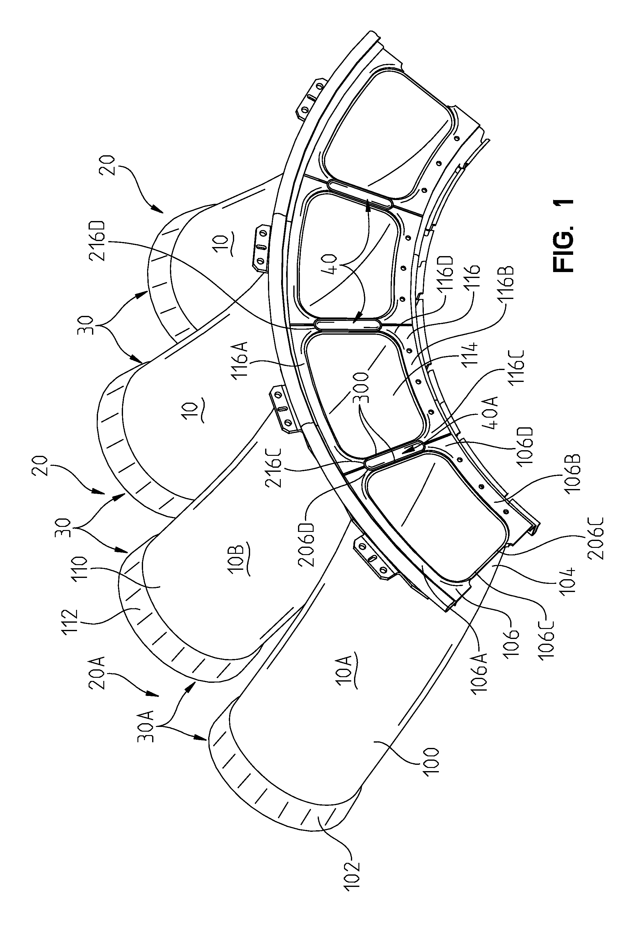
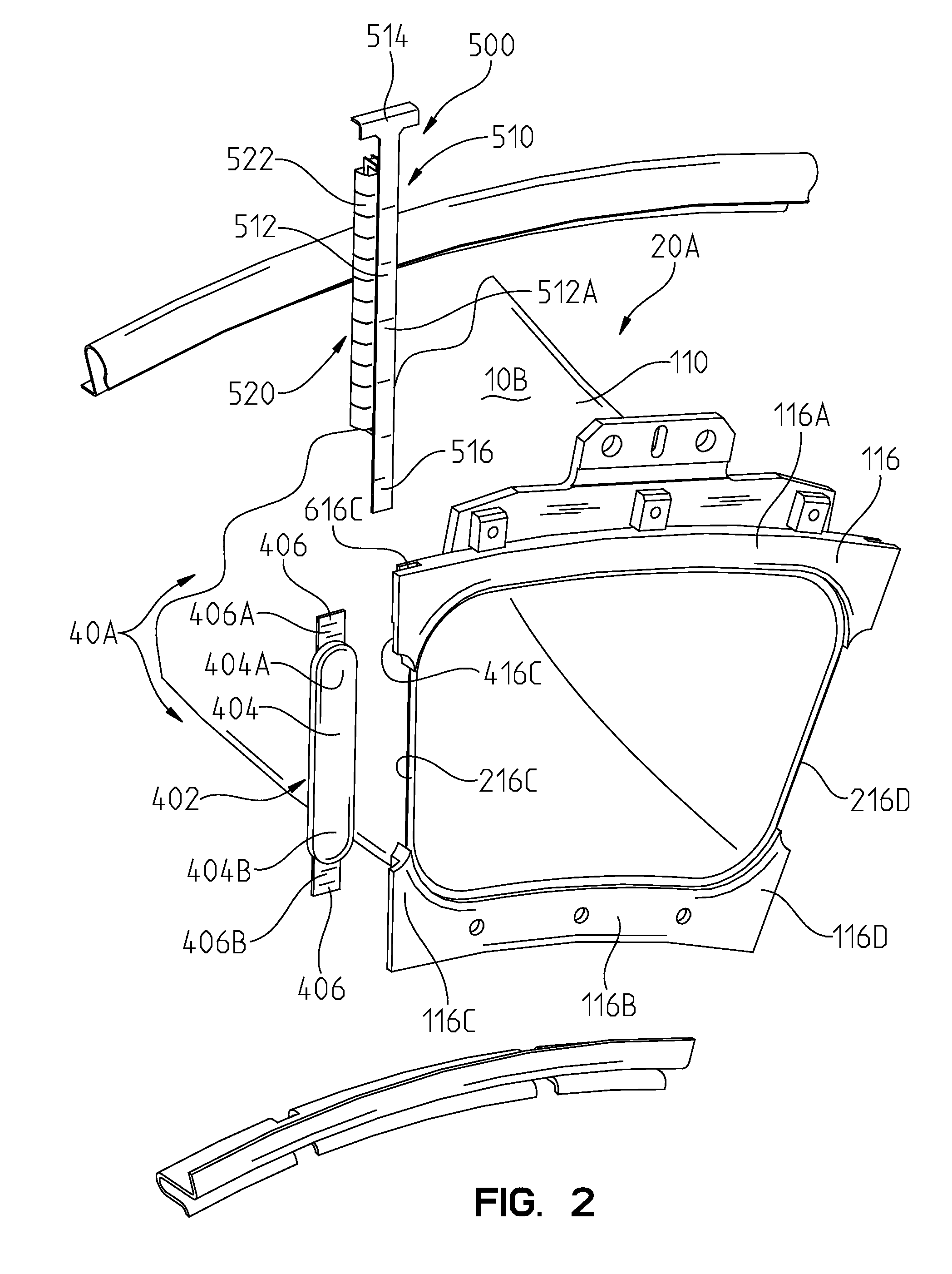
[0025]A conventional combustible gas turbine engine (not shown) includes a compressor (not shown), a combustor (not shown), including a plurality of combustor units (not shown), and a turbine (not shown). The compressor compresses ambient air The combustor units combine the compressed air with a fuel and ignite the mixture creating combustion products defining a working gas. The working gases are routed from the combustor units to the turbine inside a plurality of transition ducts 10, see FIGS. 1-3. The working gases expand in the turbine and cause blades coupled to a shaft and disc assembly to rotate.

[...


PUM


Abstract

A gas turbine transition duct is provided comprising a generally tubular main body having first and second ends, the first end being adapted to be positioned adjacent to a combustor unit and the second end being adapted to be positioned adjacent to a turbine and a collar coupled to the main body second end. The collar may have upper, lower and side portions. At least one of the side portions may be provided with a notched section.

Description

FIELD OF THE INVENTION[0001]The present invention is directed to a gas turbine transition duct having a collar with at least one notched section, a seal apparatus for sealing a relief opening defined between opposing first and second transition ducts and a gas turbine transition duct apparatus comprising first and second transition ducts and a seal apparatus.BACKGROUND OF THE INVENTION[0002]A conventional combustible gas turbine engine includes a compressor, a combustor, including a plurality of combustor units, and a turbine. The compressor compresses ambient air. The combustor units combine the compressed air with a fuel and ignite the mixture creating combustion products defining a working gas. The working gases are routed to the turbine inside a plurality of transition ducts. Within the turbine are a series of rows of stationary vanes and rotating blades. The rotating blades are coupled to a shaft and disc assembly. As the working gases expand through the turbine, the working ga...

Claims


Application Information

Patent Timeline
Patent Type & Authority Applications(United States)
IPC IPC(8): F01D25/24
CPCF01D9/023F05D2240/57F01D25/243
Inventor SCHIAVO, ANTHONY L.
Owner SIEMENS ENERGY INC
Why Eureka
Try Eureka