Method of Refraction Surgery of the Eye and a Tool for Implanting Intraocular Refractive Lens

a technology for refraction surgery and eye, applied in the field of opthalmologic surgery, can solve the problems of difficult application by many opthalmosurgeons, inability to teach the design of a tool intended for the installation of phakic lenses in the eye, and the inability to implant the refractive phakic lens into the anterior eye, so as to avoid the danger of lens damage, reduce the trauma of both the implanted piol and the surrounding eye tissue, and reduce the operation tim

Inactive Publication Date: 2010-03-04
LEONID ORBACHEVSKY
View PDF10 Cites 23 Cited by
  • Summary
  • Abstract
  • Description
  • Claims
  • Application Information

AI Technical Summary

Benefits of technology

[0031]An advantage of the present invention is that the implantable PIOL is not mechanically fixed, avoiding the lens damage danger;
[0032]Another advantage of the present invention is that the rotation of PIOL inside the cartridge and respective improper installation are impossible.
[0033]Yet another advantage for the present invention includes the level of traumatism of both implanted PIOL and the surrounding eye tissues are reduced.
[0034]Yet another advantage of the resent invention, when compared with other methods, is that operation time is reduced, because implantation is performed by a single move.
[0035]Further, the simplicity of the method allows familiarization of this operation in the high opthalmosurgeonshipm, while unitizing of the tool handle with vacuum syringe makes the tool compact and comfortable for the surgeon hand.
[0036]Further still, the tool of the present invention suggested can be provided in an inexpensive and disposable device, thereby eliminating sterilization and reduces hazard of patient's infection.

Problems solved by technology

However, the lack of complexity of the surgical technologies for current use in such implantation makes it difficult for applying by many opthalmosurgeons.
With the help of the subject instrument it is impossible to implant the refractive phakic lens into the anterior chamber of the eye because its design will cause the rupture of the lens and will damage the eye tissues (iris, crystalline lens, cornea).
While various elements within these references may possibly teach features capable of being adapted to a cannula-shaped working component in combination with a vacuum source, they do not teach a design for a tool intended for installation of phakic lenses in an eye.
In their design, certainly, there could be involved such elements as the described and anticiapted does not allow to establish phakic lens in an eye.

Method used


Image

  • Method of Refraction Surgery of the Eye and a Tool for Implanting Intraocular Refractive Lens
  • Method of Refraction Surgery of the Eye and a Tool for Implanting Intraocular Refractive Lens
  • Method of Refraction Surgery of the Eye and a Tool for Implanting Intraocular Refractive Lens

Examples


Embodiment Construction

[0046]The best mode for carrying out the invention is presented in terms of its preferred embodiment, herein depicted within the Figures.

1. Detailed Description of the Figures.

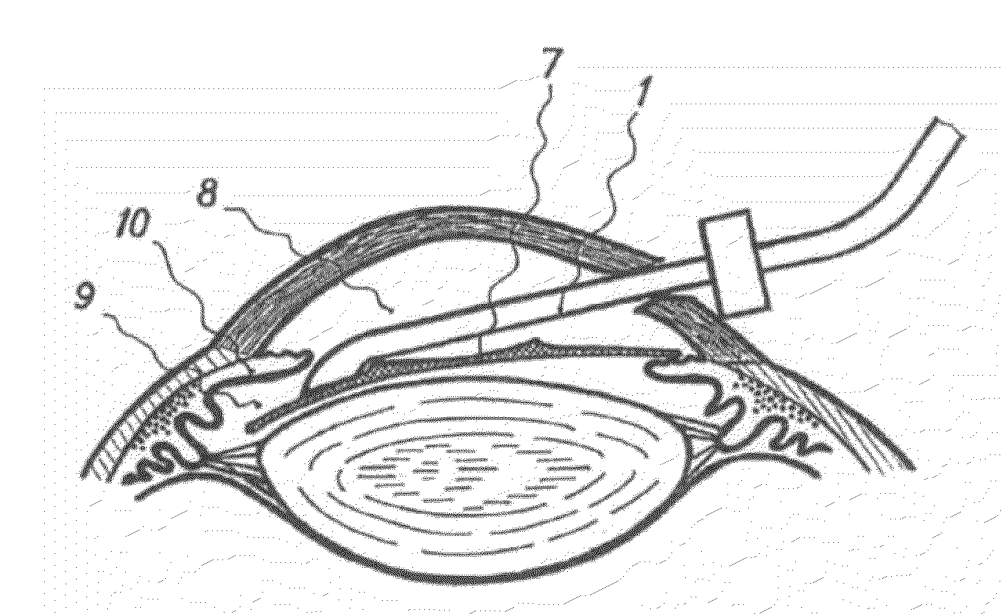
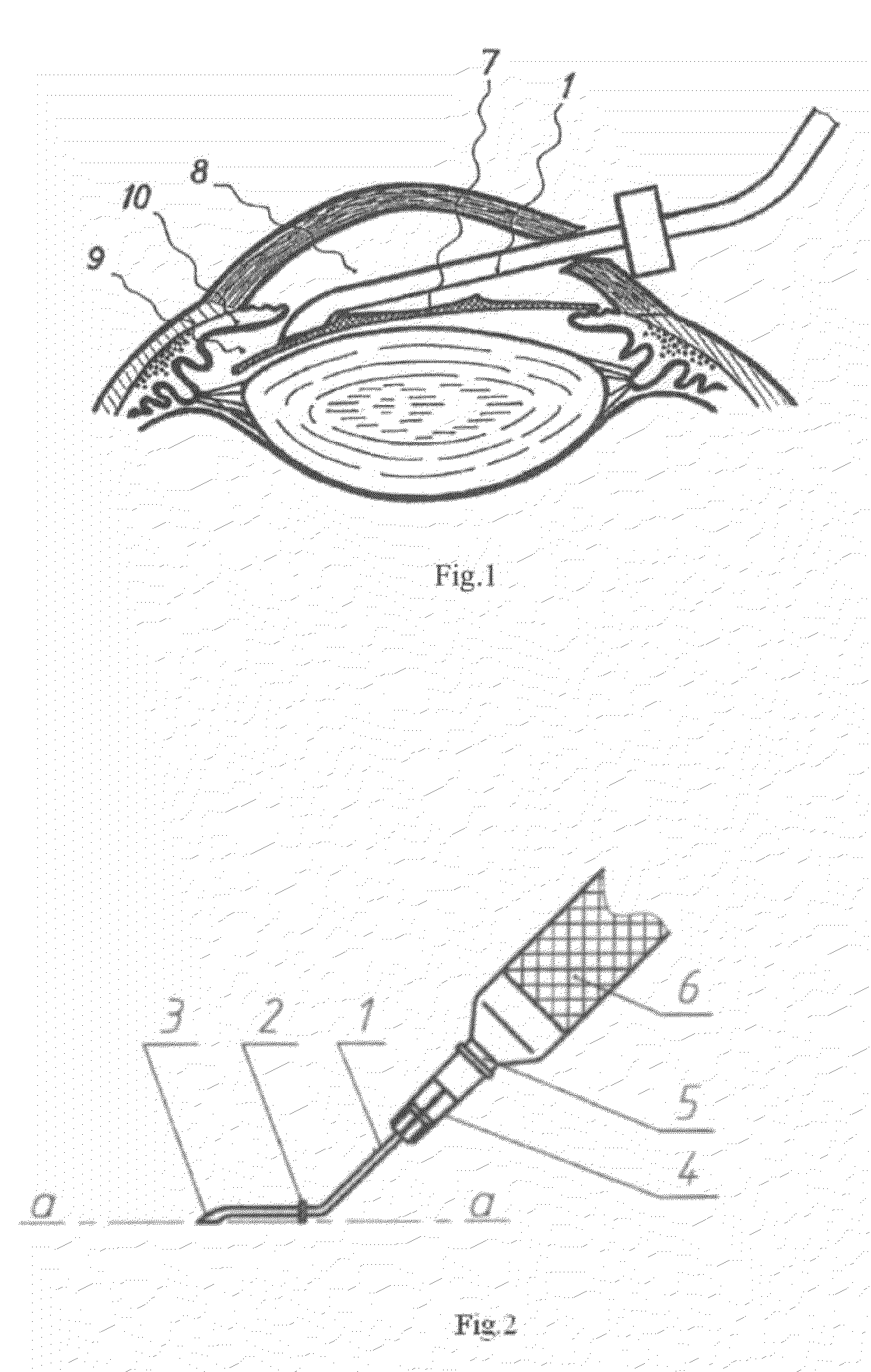
[0047]FIG. 1 shows the overall scheme of operation of the present invention. In conjunction with FIG. 2, the general overview of the device is demonstrated and shows the cannula shaped as a bent tube at an angle of between 110-160. Equipped with a limiter 2, the cannula has a V-shaped working end or face 3 when viewed from the conditional horizontal surface “a-a:. The Cannula is also supplied with a socket 4, established on the air outlet 5 of the handle 6 connected with the vacuum.

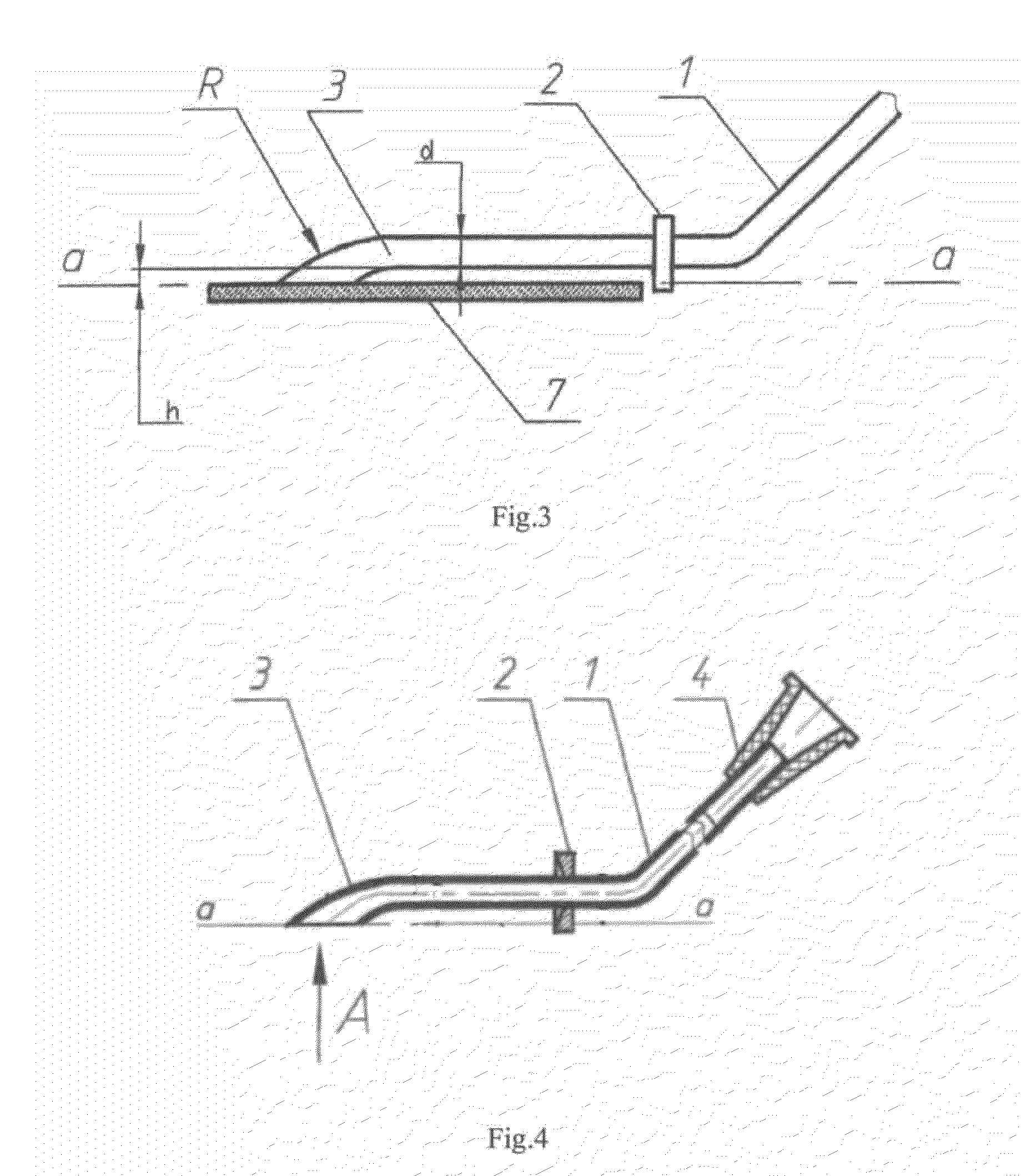
[0048]FIG. 3 shows the bend of the working end 3 fixed on the haptic part of the lens 7, at the same time the radius of the bend of the working end is not less than 2 diameters of the tube.

[0049]FIG. 4 demonstrates the design of the cannula; the limiter 2, established at the length 7-14 mm from the working end 3, is made with conica...


PUM


Abstract

A reduction of eye trauma is achieved during opthalmolic surgery branch for implanting the intraocular refractive lens to the anterior chamber of the eye. The pupil is extended by mydriatic compounds and after anesthesia the cornea cut is made (clear cornea—3 mm). Thereafter, the anterior chamber of the eye is filled with viscoelastic compound with low molecular weight and then the refractive lens is implanted with the help of said cannula, the working face of the cannula at the middle between the lens edge and the border of the optic area, with the edge bent on the cannula face. The end by the top of the bending the refractive lens is introduced into the cornea cut and set in the posterior chamber of the eye. Thereafter, vacuum is removed and the cannula is detached from the refractive lens, and taken off the anterior chamber of the eye by the reverse movement. The refractive lens cannula is made as a tube with round or oval cross-section with inner diameter 0.5-2.5 mm and wall thickness not less than 0.05 mm. The tube is bent at 110-160, supplied with limiter, and working end that has diameter of the round cross-section of 1.0-2.0 mm or ellipse-shaped cross-section with small and big axes 0.6-0.9 mm and 1.5-2.5 mm, respectively.

Description

RELATED APPLICATIONS[0001]The present invention in a Continuation in Part of U.S. Ser. No. 10 / 569,111, filed on Feb. 21, 2006, which was a National Phase application of PCT / RU2004 / 000324 having an International filing date of Aug. 18, 2004 and an International priority date of Aug. 21, 2003.BACKGROUND OF THE INVENTION[0002]1. Field of the Invention[0003]The present invention relates generally to opthalmologic surgery and, more particularly, to a opthalmologic operations for implanting intraocular refractive lens to the anterior chamber of the eye, and a tool forming a canulla for fixing a refractive phakic by vacuum to allow implantation of posterior-chamber phakic intraoccular lenses to the posterior chamber of the eye.[0004]2. Description of the Related Art[0005]Implantation of posterior-chamber phakic intraoccular lenses (referred to also as PIOL) for correction of ametropies becomes more and more popular. However, the lack of complexity of the surgical technologies for current u...

Claims


Application Information

Patent Timeline
Patent Type & Authority Applications(United States)
IPC IPC(8): A61F9/013
CPCA61F2/1664
Inventor KHURAY, ASLAN RAMAZANOVICHLATYPOV, ILYAS AMIROVICH
Owner LEONID ORBACHEVSKY
Why Eureka
Try Eureka