
Method and system to monitor, debug, and analyze performance of an electronic design

a hardware performance monitor and electronic design technology, applied in the field of electronic design automation, can solve the problems of long design cycle, slow design time to market, and limited number of fixed non-configurable parameters of the hardware performance monitor,

Active Publication Date: 2010-03-04
META PLATFORMS TECH LLC
View PDF14 Cites 35 Cited by
  • Summary
  • Abstract
  • Description
  • Claims
  • Application Information

AI Technical Summary

Benefits of technology

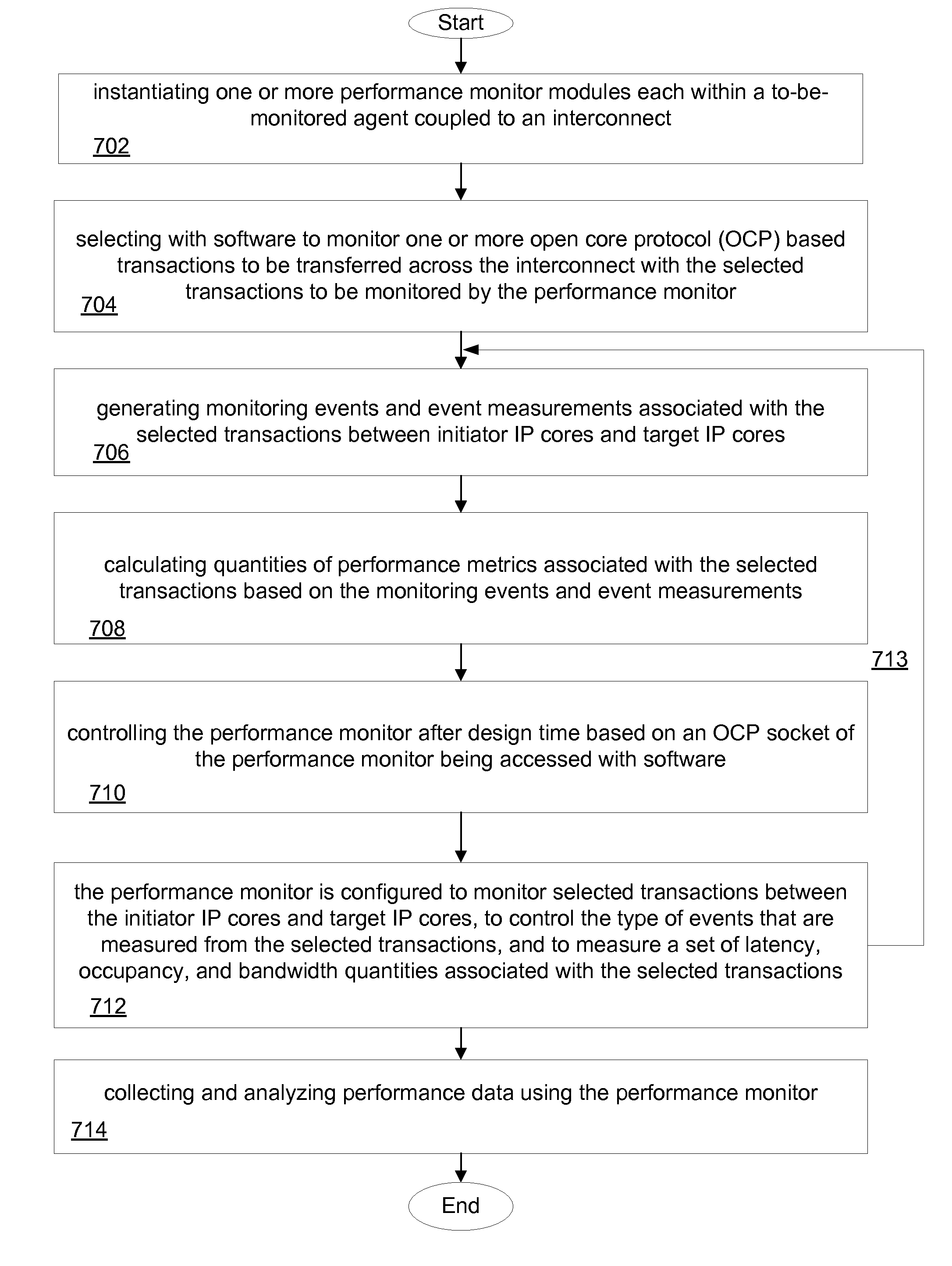
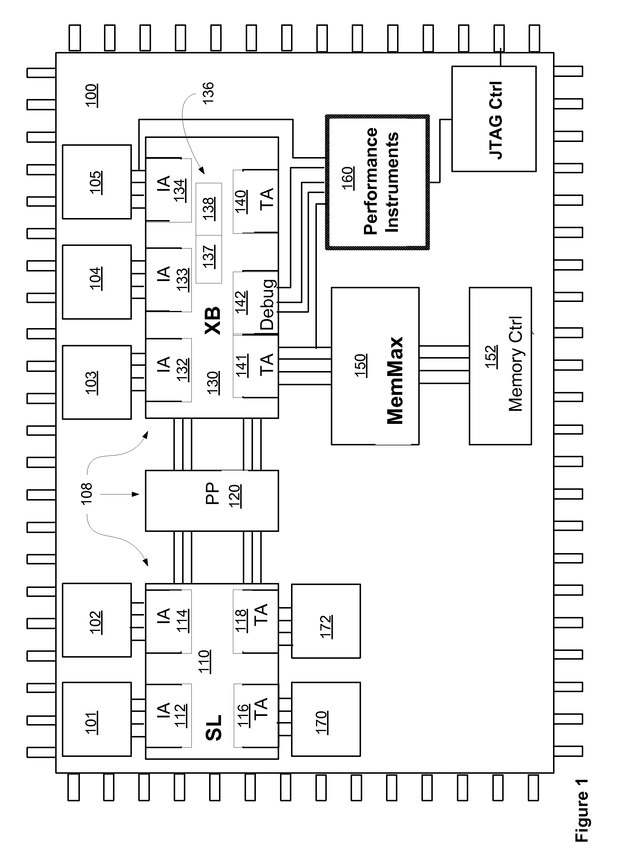
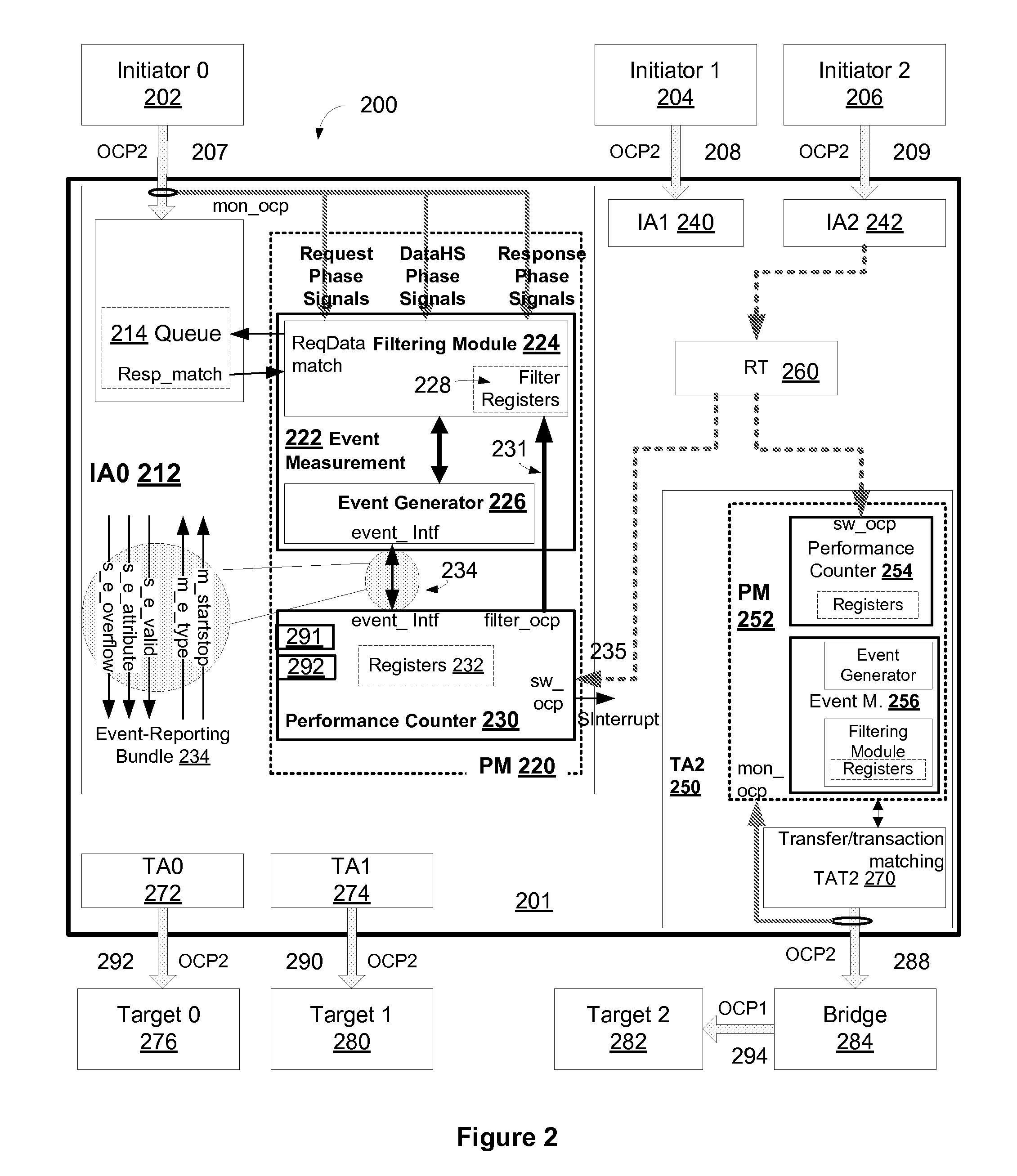
[0005]Various methods and apparatuses are described for a performance monitoring/debugging apparatus that includes an event measurement module communicatively coupled to a performance counter module. In one embodiment, the performance monitoring/debugging apparatus is located on an interconnect of a fabricated integrated circuit. The event measurement module includes an event generator sub-module that generates monitoring events and event measurements associated with transactions between initiator intellectual property (IP) cores and target IP cores over the interconnect of the fabricated integrated circuit. The event measurement module further includes a first software visible register block that provides software access for controlling the event measurement module on which one or more transactions to monitor and to configure one or more parameters associated with that transaction to track. The event measurem

Problems solved by technology

The hardware performance monitor has a limited number of fixed non-configurable parameters to be monitored.
These prior approaches are not able to quickly and efficiently monitor and analyze various parameters associated with electronic design performance early in the design cycle resulting in a longer design cycle and slower time to market for the design.

Method used


Image

  • Method and system to monitor, debug, and analyze performance of an electronic design
  • Method and system to monitor, debug, and analyze performance of an electronic design
  • Method and system to monitor, debug, and analyze performance of an electronic design

Examples


Embodiment Construction

[0021]In the following description, numerous specific details are set forth, such as examples of specific data signals, named components, connections, etc., in order to provide a thorough understanding of the present invention. It will be apparent, however, to one of ordinary skill in the art that the present invention may be practiced without these specific details. In other instances, well known components or methods have not been described in detail but rather in a block diagram in order to avoid unnecessarily obscuring the present invention. Further specific numeric references such as a first instance of a transactor, may be made. However, the specific numeric reference should not be interpreted as a literal sequential order but rather interpreted that the first instance of a transactor is different than a second instance of a transactor. Thus, the specific details set forth are merely exemplary. The specific details may be varied from and still be contemplated to be within the ...


PUM


Abstract

Various methods and apparatuses are described that provide instrumentation and analysis of an electronic design. A performance monitoring apparatus may be located on an interconnect of a fabricated integrated circuit. An event measurement module (EM) includes an event generator sub-module that generates monitoring events and event measurements associated with transactions between initiator intellectual property (IP) cores and target IP cores over the interconnect. The EM further includes a software visible register block that provides software access for controlling the EM on which one or more transactions to monitor and to configure one or more parameters associated with that transaction to track. The EM further includes a filtering sub-module that selects transactions to be monitored based on information received from the software. The performance counter module aggregates events and event measurements received from the EM into quantities of performance metrics associated with transactions between the IP cores over the interconnect.

Description

NOTICE OF COPYRIGHT[0001]A portion of the disclosure of this patent document contains material that is subject to copyright protection. The copyright owner has no objection to the facsimile reproduction by anyone of the software engine and its modules, as it appears in the Patent and Trademark Office Patent file or records, but otherwise reserves all copyright rights whatsoever.FIELD OF THE INVENTION[0002]Embodiments of the invention generally relate to electronic design automation. An aspect is related to monitoring and analyzing an electronic design with a hardware performance monitor.BACKGROUND OF THE INVENTION[0003]Many electronic designs are written at a register-transfer level (RTL) description of a circuit or system in a hardware description language. Generally, a RTL description describes what intermediate information (i.e. information stored between clock cycles in an electronic circuit) is stored in registers, where it is stored within the design, and how that information ...

Claims


Application Information

Patent Timeline
IPC IPC(8): G21C17/00
CPCG06F11/3466G06F11/3471G06F2201/88G06F2201/86G06F2201/87G06F11/348
Inventor CHOU, CHIEN-CHUNHAMILTON, STEPHEN W.WINGARD, DREW E.CHAUVET, PASCAL
Owner META PLATFORMS TECH LLC
Learn More