Rotation control system for working-machine pump
a technology of rotating control system and hoist pump, which is applied in the direction of positive displacement liquid engine, fluid coupling, servomotor, etc., can solve the problems of excessive strain on the hydraulic oil tank, cumbersome efforts, and complicated structure, and achieve the effect of more precise control of the rotation speed
- Summary
- Abstract
- Description
- Claims
- Application Information
AI Technical Summary
Benefits of technology
Problems solved by technology
Method used
Image

Examples
first exemplary embodiment
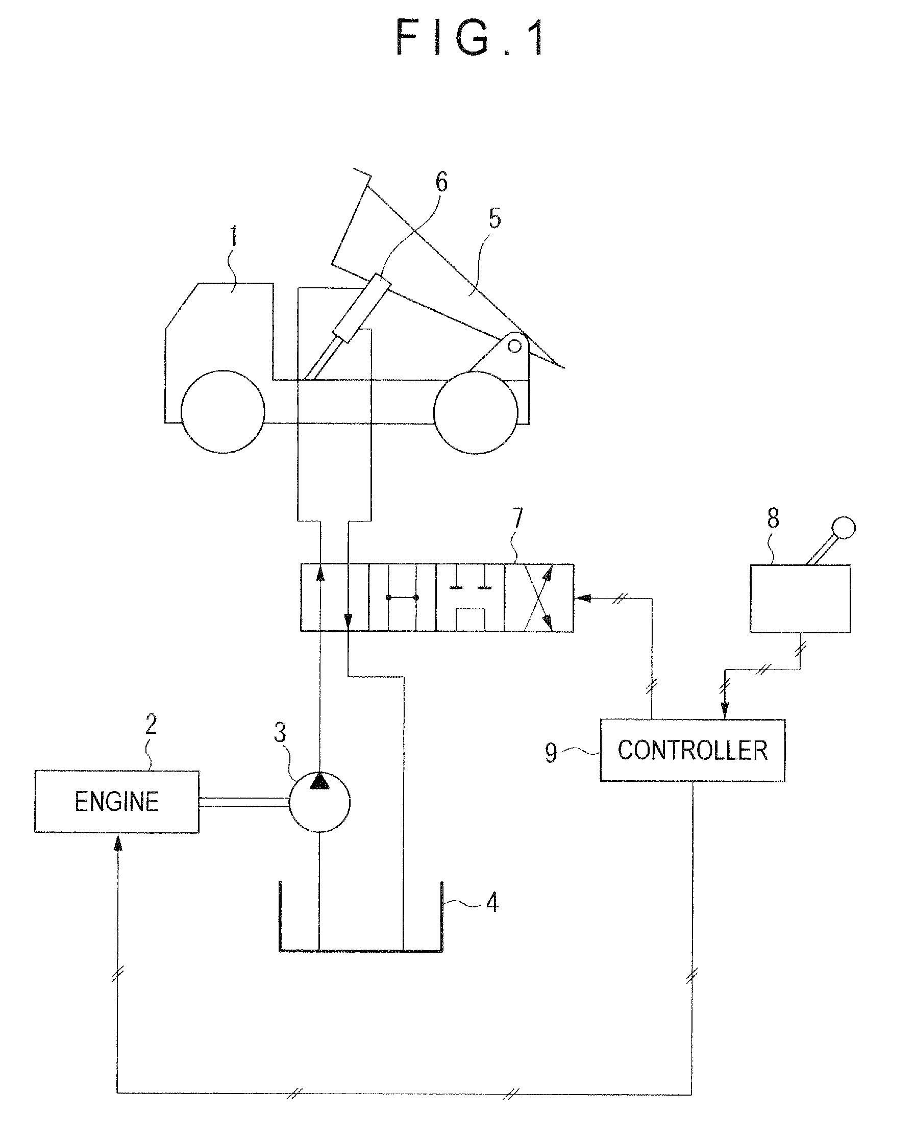
[0043]FIGS. 1 to 3 show the first exemplary embodiment of a rotation control system of a hoist pump of the invention. FIG. 1 schematically shows a hydraulic circuit of the rotation control system of the hoist pump. The system controls a rotation speed of a hoist pump 3 when a body 5 provided on a dump truck is lifted up and down, thereby preventing cavitation within the hoist pump 3.
[0044]The hoist pump 3 has a constant capacity in the first exemplary embodiment, but may have a variable capacity.
[0045]As shown in FIG. 1, a vehicle body 1 of the dump truck includes: an engine 2; the hoist pump 3 driven by the engine 2; and a hydraulic oil tank 4 for storing hydraulic oil delivered through the hoist pump 3. The body 5 vertically movable is provided on a rear portion of the vehicle body 1. The body 5 and the vehicle body 1 are connected via a hoist cylinder 6 provided by a matched pair of hydraulic cylinders. A hoist valve 7 serving as a switching valve switches a flow of hydraulic oil...
second exemplary embodiment
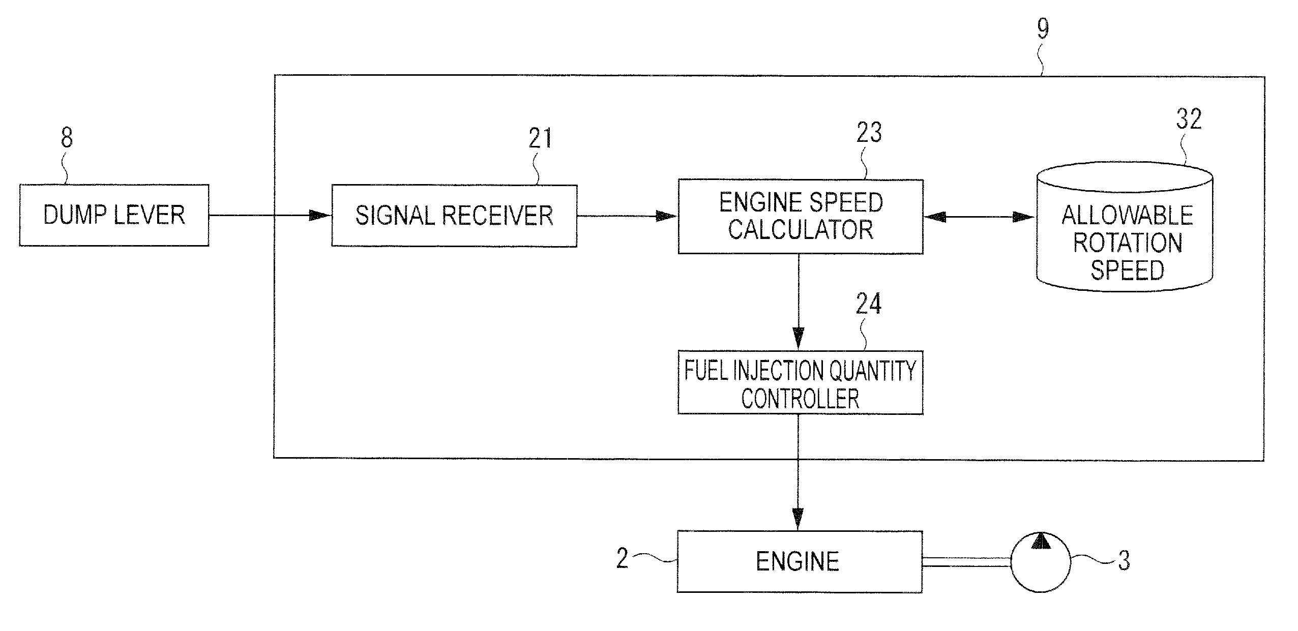
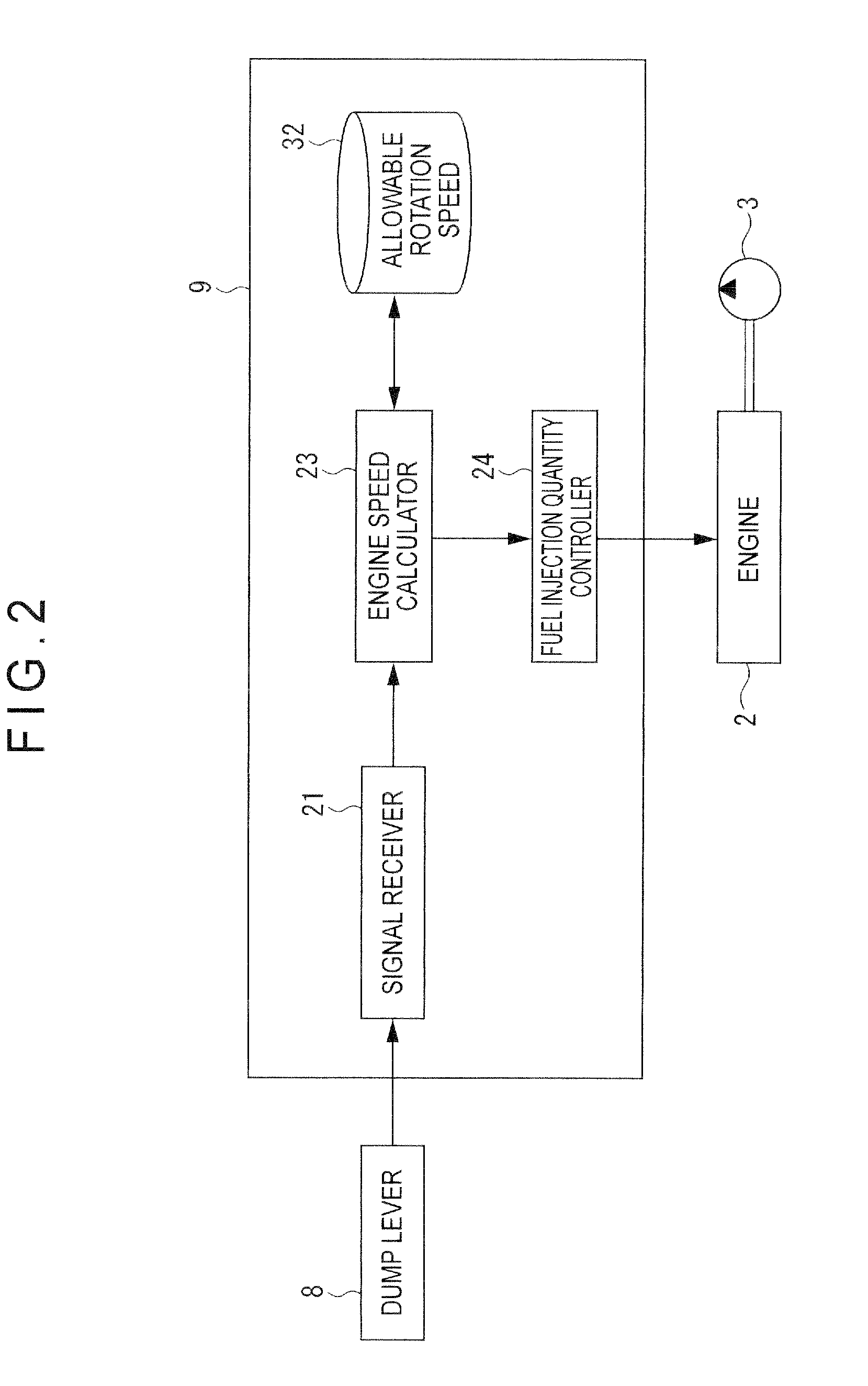
[0055]FIGS. 4 to 6 show a second exemplary embodiment of the rotation control system of the hoist pump of the invention. FIG. 4 schematically shows a hydraulic circuit of the rotation control system of the hoist pump according to the second exemplary embodiment. In this exemplary embodiment, a seating sensor 17 serving as a position sensor detects the elevating operation of the body 5. The seating sensor 17 outputs a seating signal when the body 5 is seated and does not output the seating signal when the body 5 is lifted up.
[0056]As shown in FIG. 4, the vehicle body 1 of the dump truck includes the seating sensor 17 on a position where the body 5 is lifted down and seated. Thus, the seating signal is inputted to the signal receiver 21 of the controller 9 as shown in FIG. 5 when the body 5 is seated. Other arrangements are the same as those of the first exemplary embodiment.
[0057]Similarly to the first exemplary embodiment, data of the allowable rotation speed of the hoist pump 3 pre...
third exemplary embodiment
[0061]FIGS. 7 to 9 show a third exemplary embodiment of the rotation control system of the hoist pump of the invention. FIG. 7 schematically shows a hydraulic circuit of the rotation control system of the hoist pump according to the third exemplary embodiment. In this exemplary embodiment, an inclination position of the body 5 is consecutively measured by a potentiometer 10. When the potentiometer 10 determines that the body 5 is lifted up, the rotation speed of the hoist pump 3 is controlled by the controller 9.
[0062]As shown in FIG. 7, the vehicle body 1 of the dump truck includes the potentiometer 10 for measuring the inclination position of the body 5 on a position where the body 5 and the vehicle body 1 are connected to each other. Thus, a position measurement signal is consecutively inputted from the potentiometer 10 to the signal receiver 21 of the controller 9 as shown in FIG. 8. Other arrangements are the same of those of the first exemplary embodiment.
[0063]In particular, ...
PUM
 Abstract
Description
Claims
Application Information
 - R&D Engineer
- R&D Manager
- IP Professional
- Industry Leading Data Capabilities
- Powerful AI technology
- Patent DNA Extraction
Browse by: Latest US Patents, China's latest patents, Technical Efficacy Thesaurus, Application Domain, Technology Topic.
© 2024 PatSnap. All rights reserved.Legal|Privacy policy|Modern Slavery Act Transparency Statement|Sitemap