
Electrical circuit diagnostic tool

a technology of electrical circuit and diagnostic tool, which is applied in the direction of testing electric installations on transport, fault location by increasing the damage at the fault, instruments, etc., can solve the problems of inability to diagnose, inconvenient use, and inability to accurately read voltag

Inactive Publication Date: 2010-03-11
BLUELINK DIAGNOSTIC SOLUTIONS
View PDF10 Cites 9 Cited by
  • Summary
  • Abstract
  • Description
  • Claims
  • Application Information

AI Technical Summary

Benefits of technology

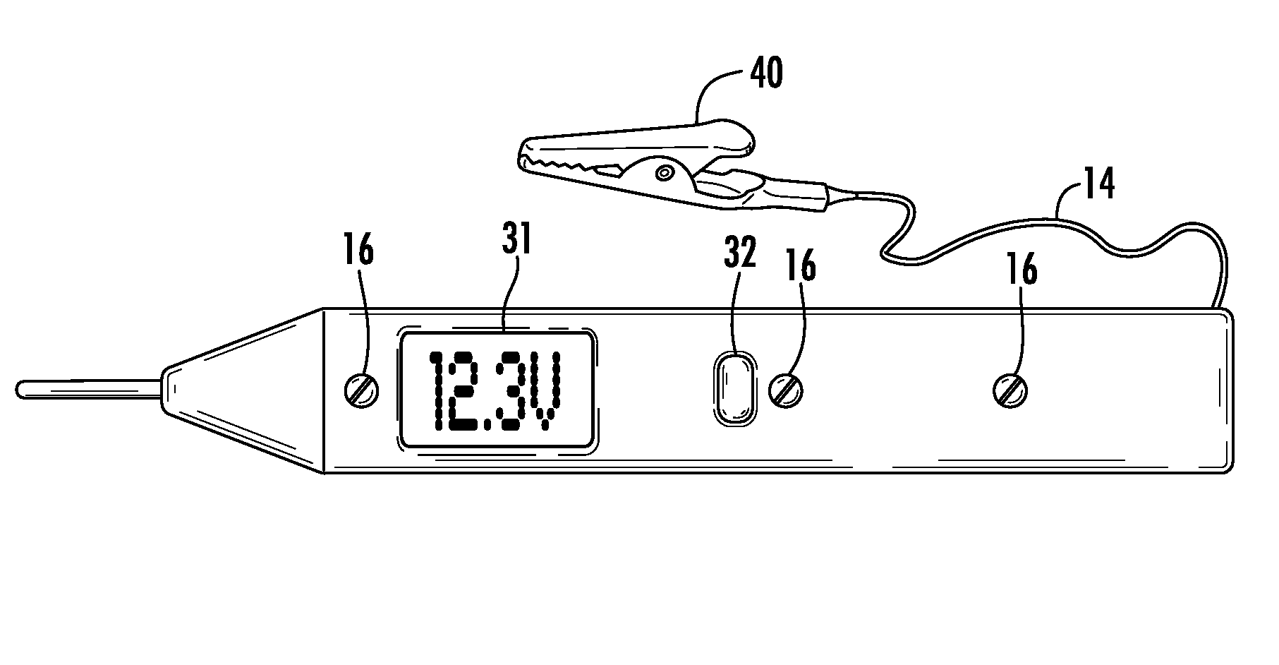
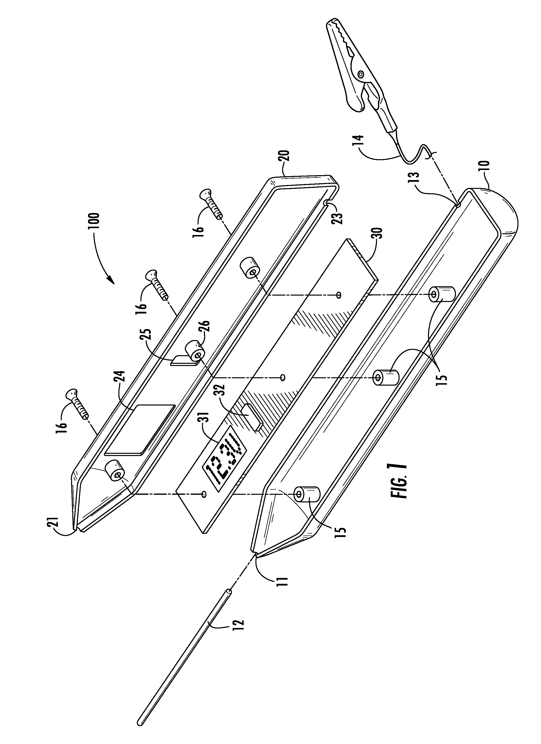
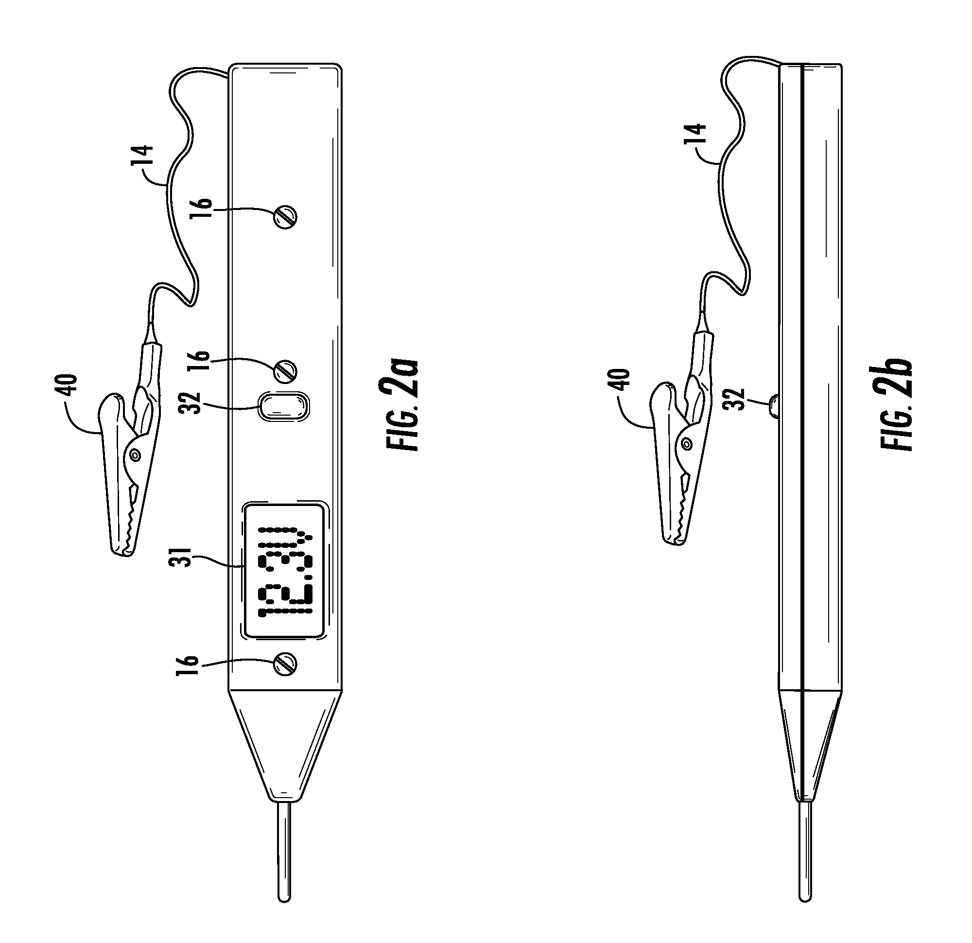
[0018]It is an objective of the diagnostic tool of the present invention to be able to automatically determine voltage drop across measured elements of an electrical circuit. It is a further objective of the present invention to be able to automatically determine voltage drop across measured elements of a motor vehicle electrical system thereby determining whether a given circuit element or device is defective or whether such circuit element or device “tests bad” because the electrical system is incapable of delivering adequate current and / or a minimum required voltage.

Problems solved by technology

Voltmeters are high-impedance devices intended to measure a point contact without loading the measured circuit, since circuit loading can cause the circuit characteristics to change and thereby yield an incorrect voltage reading.
While each of the above diagnostic tools are useful in varying instances, the cost of the device, limited diagnostic ability, and need for varying degrees of user skill limits the usefulness of such tools in certain applications.
However, there currently exists no diagnostic tool that combines the ease of use of a conventional voltmeter with the ability to automatically measure a voltage under a varying load and determine the load at which the point contact measurement crosses a minimum value.

Method used


Image

  • Electrical circuit diagnostic tool
  • Electrical circuit diagnostic tool
  • Electrical circuit diagnostic tool

Examples


Embodiment Construction

[0027]As a preliminary matter, it will readily be understood by one having ordinary skill in the relevant art (an “Ordinary Artisan”) that the present invention has broad utility and application. Furthermore, any embodiment discussed and identified as being “preferred” is considered to be part of a best mode contemplated for carrying out the present invention. Other embodiments also may be discussed for additional illustrative purposes in providing a full and enabling disclosure of the present invention. Moreover, many embodiments, such as adaptations, variations, modifications, and equivalent arrangements, will be implicitly disclosed by the embodiments described herein and fall within the scope of the present invention.

[0028]Accordingly, while the present invention is described herein in detail in relation to one or more embodiments, it is to be understood that this disclosure is illustrative and exemplary of the present invention, and is made merely for the purposes of providing ...


PUM


Abstract

Diagnosing electrical circuit faults can be accomplished with a variety of tools. Voltmeters are frequently used to measure voltage to determine whether a short is present, but are not well-suited for finding intermittent faults caused by corroded connectors or excessive voltage drop under operating loads. Measuring a static voltage without load using a voltmeter can yield misleading results. A diagnostic tool that is simple to use and that yields a definitive result is preferred in certain applications such as automotive electrical system diagnosis due to the varying skill level of technicians and the variation in field conditions in automotive shops. A simple, inexpensive diagnostic tool that can be used with minimal or no training allows rapid diagnosis of circuit faults that result from a the inability of a measured circuit to supply a minimum current at a minimum voltage.

Description

COPYRIGHT STATEMENT[0001]All of the material in this patent document is subject to copyright protection under the copyright laws of the United States and of other countries. The copyright owner has no objection to the facsimile reproduction by anyone of the patent document or the patent disclosure, as it appears in the Patent and Trademark Office patent file or records, but otherwise reserves all copyright rights whatsoever.BACKGROUND OF THE INVENTION[0002]1. Field of the Invention[0003]The present invention generally relates to a diagnostic tool that can measure voltage under controlled conditions and vary a point load in order to determine the capacity of a given circuit to operate under typical or extreme conditions rather than ideal conditions.[0004]2. Background[0005]A conventional voltmeter measures voltage at a given point in a circuit using a high-impedance input. The goal with such a voltmeter is to determine the voltage present at the measured contact point without imposin...

Claims


Application Information

Patent Timeline
Patent Type & Authority Applications(United States)
IPC IPC(8): G01R31/28
CPCG01R1/06788G01R31/006G01R15/12
Inventor BECKMANN, ROBERT U.
Owner BLUELINK DIAGNOSTIC SOLUTIONS
Learn More